
Components:
1. Local loops (twisted pairs, analog signaling or N-ISDN)
2. Trunks (fiber optics or microwave, mostly digital)
3. Switching offices

An electrical signal is distorted when it is transmitted over a wire, because higher frequencies are more diminished than lower frequencies, If all the harmonics were equally diminished, the resulting signal would be reduced in amplitude but not distorted. Usually the amplitudes are transmitted relatively undiminished up to a cutoff frequency, above which the amplitudes are strongly attenuated.
Nyquist proved in 1924 that if an arbitrary signal has been run through a low-pass noiseless filter of bandwidth H, the filtered signal can be completely reconstructed by taking only 2H (exact) samples per second. This one calls the number of bauds per second. If that signal has V discrete levels the maximum data rate is 2H log2V bits/sec. Thus a noiseless 3 kHz channel cannot transmit binary (2 level) signals at a rate exceeding 6000 bps.
Shannon showed in 1948 that if there is random noise present on a channel with a bandwidth of H Hz, that the maximum number of bps is H log2 (1+S/N). Here the noise is measured as the ratio S/N of signal power to noise power, the signal-to-noise ratio. This is often given in units of decibel (dB): 10 log10 S/N. Thus a channel of 3 kHz and 30 dB, typical parameters of the analog part of the telephone system, cannot transmit much more than 30,000 bps no matter how much signal levels are used. The limit is not in the wire between home and the telephone office but in the electronic equipment there.
Thus 30 Kbps is about the maximum modem speed on a fully analog connection.
Read it to get acquainted with some terms: twisted pair, UTP category 3 and 5, baseband and broadband coaxial cable, multimode and single-mode fiber.
Read it to get acquainted with some terms: frequency hopping spectrum, direct sequence spread spectrum, ISM bands.
Not needed
PSTN (Public Switched Telephone Network)
|
Components: |
 |
Transmission problems: |
Modems (modulator-demodulator)
 |
Avoid DC signaling, due to high frequency components. Use a continuous tone in the 1000 to 2000 Hz range, called a sine wave carrier, and modulates its amplitude, frequency or phase. Modems use a combination of these to transmit multiple bits per baud. V.32 9600 bps modems use 3 bits per baud, V.32bis use 6 bits per sample at 2400 baud. V.34 runs at 28k8 (28800 bps) and V.34bis at 33k6, the maximum you can get from a good telephone line. If the connection is of bad quality, the modem switches to a lower rate. |
V.90 56 kbps modem: 56k downstream only if the other side (e.g. the Internet Service Provider) is digitally (e.g. ISDN) connected to the telephone system, as is ISP 2 in the above image. Upstream (from user to ISP) 33k6 is used. In theory is could be higher, but more bandwidth is allocated to the downstream channel to ensure that 56k can be reached in more cases of a bad analog line between user and end office.
Compression and error correction are often built into the modems. MNP5 uses run-length encoding, V.42bis uses Ziv-Lempel compression. This helps to increase the effective transfer rate for uncompressed files and information. Make sure that the serial port on the computer can handle the higher rate.
Narrowband ISDN (not in Tanenbaum)
 |
 |
 |
The basic rate ISDN provides 2 B channels of 64 kbps digital PCM (see 2.5.4) for voice or data and 1 D channel for out-of-band signaling. The primary rate provides 30B + 1D channels and fits in the E1 carrier (see 2.5.4), for US and Japan this is 23B + 1D to fit in the T1 carrier. It is used for connecting PBX (Private Branche Exchanges) for middle and large business.
The basic rate is now popular in the Netherlands for home use as it provides 2 digital 64 kbps telephone connections at a lower cost than 2 analog telephone lines (currently fl 50.58 compared to 2 x fl 35.05 per month in the Netherlands, the price per second per call is the same). The ISDN lines go over 1 line between home and central office, so no digging is required to install it. Analog telephones can be used via converters, which are often included in the ISDN cards or external boxes which connect to the serial port of a computer. The S bus can be 160 m long, the wires to the telephones or computers can be 10 m long.
ADSL Asymmetric Digital Subscriber Line)
 The available 1.1 MHz spectrum on the standard local loop (category 3 twisted pair)
is divided in 256 4 kHz channels. The lower ones are used for analog telephone, ISDN
and control channels. The higher ones are divided asymmetrically in channels for upstream
and downstream communication. The standard offers 8 Mbps downstream and 1 Mbps upstream, but most providers
like KPN offer lower speeds. The maximum obtainable rate depends on the distance between home and end office,
see fig 2-27 for an indication.
The available 1.1 MHz spectrum on the standard local loop (category 3 twisted pair)
is divided in 256 4 kHz channels. The lower ones are used for analog telephone, ISDN
and control channels. The higher ones are divided asymmetrically in channels for upstream
and downstream communication. The standard offers 8 Mbps downstream and 1 Mbps upstream, but most providers
like KPN offer lower speeds. The maximum obtainable rate depends on the distance between home and end office,
see fig 2-27 for an indication.
 Splitters are used to separate analog telephone, ISDN and ADSL signals.
NID: Network interface device
Instead of Ethernet also USB modems can be used.
Because it costs a lot of money to install a trunk cable, due to the digging, telephone companies have developed ways of multiplexing many conversations over a single physical trunk:
 |
Filters limit the bandwidth of voice grade telephone channels to about 3 kHz. Twelve 4 kHz channels (3 kHz plus two guard bands of 500 Hz) are multiplexed into the 60 tot 108 kHz band. Five of these groups can be multiplexed to form a supergroup. Different standards are used around the world for multiplexing and grouping. FDM requires analog circuitry, therefore it has been mostly replaced by TDM, which can be handled entirely by digital computers. |
For TDM the analog signals are digitized by a codec (coder-decoder) producing a 7 or 8 bit number at a rate of 8000 samples per second. This is called PCM (Pulse Code Modulation). Virtually all time intervals within the modern telephone system are 125 micro-seconds, the time of 1 sample.
 |
The T1 carrier is in use in North America and Japan. 24 voice channels are multiplexed, usually using 1 codec on a round robin basis. When the T1 is used entirely for data, the 24th channel is used for synchronizing, to reduce the error rate. In Europe the CCITT E1 carrier is used. It packs 32 8-bit samples into the basic 125 us frame, two of them are used for signaling. The digitized voice signals can be (lossy) compressed using various techniques like DCPM, delta modulation or predictive coding. |
 |
Multiple T1 streams can be further multiplexed onto higher carriers. Also the E1's can be multiplexed in a different way. T1 and E1 can be leased by companies to links their PBX (Private Branch eXchange) or LAN's at different locations. |
Wavelength Division Multiplexing
 Products of 96 channels of 10 Gbps are on the market. Systems of 200 channels are under development.
An imported other development is all optical amplifiers to be placed every 1000 km on the fiber.
They replace replacing the electrical ones (including opto-electrical conversions), which were needed
every 100 km.
SONET/DSH skip it for this course.
 |
The current telephone systems use circuit switching. When a call is made, a dedicated path is created between both ends which will exist until the call is finished. The path functions as a physical copper connection, although inside the switches it exists as packets being transmitted inside a computer from I/O port to I/O port. |
 |
Timing of events in (a) circuit switching, (b)message passing , (c) packet switching. |

GSM (Global System for Mobile communications)
GSM has been designed as a fully digital system, without compromises for the sake of backward compatibility (e.g. having to use existing frequency slots). It was originally designed for use in the 900 MHz band, but later a second system DSC 1800 (also called GSM1800 or Extended GSM) was set up using the 1800 MHz band. The GSM specification is about 6000 pages long, a large fraction relates to engineering aspects, like the receivers to handle multipath (reflections) signal propagation and synchronizing transmitters and receivers.
 |
GSM uses FDM, 124 pairs of channels, each 200 kHz wide. An 8-slot TDM is
used on each channel. The TDM slots are part of a complex framing
hierarchy, part of which, the 26-slot multiframe, is shown. |
 |
In addition also a 51-slot multiframe is used. Some of these slots are used to hold control channels. The common control channel consists of 3 logical subchannels. The paging subchannel is used by the base station to announce incoming calls, it is monitored continuously by each mobile telephone. The random access subchannel runs a slotted ALOHA system to allow a mobile station to request a call. This is answered on the access grant subchannel. |
 |
 |
A base transceiver (the fixed transmitter-receiver of GSM) can only use about 1/7 of the frequency channels to avoid interference with neighboring transceiver. This amounts to about 124/7 * 8 = 136 telephone connections. If more active mobile stations must be served in a given area, the area is splitted into 7 smaller cells. |
 |
Each base station uses the broadcast control channel in the 51-slot multiframe to continuously send its identity and status. A moving mobile GSM telephone monitors the signal strength of neighboring base stations to determine in which cell it is and whether it has crossed a cell boundary. The dedicated control channel is used to handle the location changes and also the registration and setup of a call request. |
CMDA Code Division Multiple Access
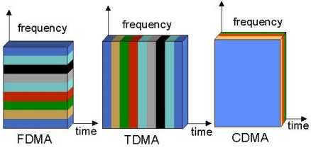 |
In CMDA each station sends over the full available spectrum all of the time. Each bit time is divided into m intervals called Chips. Each station has an unique m-bit code, its chip sequence. To transmit a '1' a station sends its chip sequence, to transmit a '0' the one's complement of it. |
 |
Four stations with their 8-bit chip sequences, also given in bipolar notation to make the discussion easier.
If B and C send a 1 bit and the others nothing, the received power add up to the sequence S2.
The bit send by C can be recovered by taking the normalized inner product of S2 and the sequence of C.
This works because of orthogonality conditions are imposed on chips sequences:
A.B = (1+1-1-1+1-1+1-1)/8 = 0 and A.A = (1+1+1+1+1+1+1+1)/8 = 1. This assumes that the stations are synchronized in time. In practice, the receiving station synchronizes on the station it wants to decode, using a certain known sequence. Time difference with other sending stations can then be regarded as introducing noise. The longer the chip sequence the higher the probability of correctly decoding the send bit. For extra reliability the bit sequence (never the chip sequence) can use an error-correcting code. |
Another assumption is that the power levels of all stations are the same as perceived by the receiver. This is more or less achieved by letting mobile stations transmit with a power proportional to the inverse of the power received from the fixed base station.
CMDA is used in certain second generation mobile systems in the US. It will also be used in the third generation UMTS system in Europe, if it comes (see 2.6.3).
 |
The original cable television is downstream only, from the headend to the individual houses, which tap into a common coaxial cable. There is room for 60-80 TV channels and it does not matter whether there are 10 or 10.000 viewers. But for Internet it does matter because the available bandwidth must be shared by many users. Also the speed of a connection of a certain user is dependent on what others are doing. To adapt a cable for bidirectional data transfers splitters and electronics must be placed at the end of the coax cables. These headends must be connected via fibers to an ISP. The frequency channels above the TV channels are used for downstream data, how far one can go depends on the quality of the coax cable and of the taps. In each channel of 6 MHz (8 MHz in Europe) the maximum data rate is 27 Mbps (higher in Europe), but this is seldom reached. This rate must be shared by many users. Frequencies below the TV channels are used for upstream channels, the maximum rate here is 9 Mbps per channel. These channels are more complicated than the downstream channels because there are many senders which must content for the bandwidth. |
 |
The rates offered to users is lower, typically 1.5 Mbps and 0.128 Mbps, and there is no guaranty on it. The connection to the ISP and the capacity of the servers there is also a limiting factor. |
Read 2.7.5 for a comparison between ADSL and Cable.
Gewijzigd op 28 januari 2003 door Theo Schouten.