Real-time Linux (Xenomai)
Radboud University Nijmegen
Exercise #7: Interrupt Service Routines
Note: This exercise cannot be done on a simulated version of Xenomai, but requires a Rhaspberry Pi with breadboard.
Introduction
Interrupt handling is important in real-time operating systems, because via the interrupt mechanism the system becomes aware of external events. The speed of the system's response to interrupts is an important characteristic of many real-time systems.
Objectives
The following are the primary objectives of this exercise:
- To get some experience with reading and writing GPIO pins on the Raspberry Pi using Xenomai.
- To get some experience with interrupt handling using a GPIO pin on the Raspberry Pi using Xenomai.
Description
The interaction with GPIO pins in real time with Xenomai requires a real-time device driver.
Device driver
For every new piece of hardware that is added to a computer, the computer needs a so called hardware driver to interact with it. For linux, a hardware driver is implemented using a kernel module. Such a hardware driver is made accessible to user space by a so called device file. A user space program can interact with the hardware by opening this device file using the open function:
int fd=open("/dev/devicefile", ...)
The open call returns a file handle to the device. This handle can be used to the read data from the device
or write data to the device using the
read and
write
functions. For instance,
    int value;
    read(fd1, &value, 4);
    write(fd2, &value, sizeof(value));
Note that to read and write a single GPIO pin two file handles are needed that have to be initialized as described below. Basically linux uses the file API to interract with an device by representing a device as a virtual file. Devices, however, are often more complex and they support more specialized interactions then just reading and writing data. For these other interactions, linux supports the ioctl function which has the following interface:
int ioctl(int fd, int request, ...);
The first argument fd must be an open file descriptor for a device.
The second argument is a device-dependent request code. The third argument is an untyped pointer to memory which usage depends on the specific request code.
In this way, several request codes can be provided to implement specialized interactions for a particular device.
Real-time device driver
The GPIO pins on the Raspberry Pi can be controlled from linux using a device driver in /dev/ where for each pin there is a separate driver to control it. When using a linux device driver in Xenomai, however, program execution moves from the high priority real-time kernel to the low priority of the linux kernel. Hence specialized drivers are needed for the real-time kernel.Xenomai uses the Real-Time Driver Model (RTDM) to implement real-time drivers. In these exercises we use an already implemented RTDM driver for the GPIO pins on the Raspberry Pi called xeno_gpio.
The image on the sd-card used in this course automatically loads the xeno_gpio RTDM device driver on boot. The can be seen by typing "lsmod" on the command line, which lists the currently loaded kernel modules:
    $ lsmod
    Module                  Size  Used by
    xeno_gpio               5816  0                       <===  RTDM device driver for GPIO pins
    brcmfmac              174972  0
    brcmutil                5401  1 brcmfmac
    cfg80211              407645  1 brcmfmac
    rfkill                 15887  2 cfg80211
    snd_bcm2835            19446  0
    bcm2835_gpiomem         2832  0
    bcm2835_rng             1743  0
    snd_pcm                72236  1 snd_bcm2835
    snd_timer              18808  1 snd_pcm
    snd                    49809  3 snd_bcm2835,snd_timer,snd_pcm
    uio_pdrv_genirq         2940  0
    uio                     7652  1 uio_pdrv_genirq
    ipv6                  343411  38
To separate the RTDM device drivers from the linux device drivers, their device file is in the /dev/rtdm/ sub-directory.
For each GPIO pin there is such a file :
    $ cd /dev/rtdm/pinctrl-bcm2835/
    $ ls
    gpio0   gpio12  gpio16  gpio2   gpio23  gpio27  gpio30  gpio34  gpio38  gpio41  gpio45  gpio49  gpio52  gpio9
    gpio1   gpio13  gpio17  gpio20  gpio24  gpio28  gpio31  gpio35  gpio39  gpio42  gpio46  gpio5   gpio6
    gpio10  gpio14  gpio18  gpio21  gpio25  gpio29  gpio32  gpio36  gpio4   gpio43  gpio47  gpio50  gpio7
    gpio11  gpio15  gpio19  gpio22  gpio26  gpio3   gpio33  gpio37  gpio40  gpio44  gpio48  gpio51  gpio8
The command rmmod xeno_gpio unloads the xeno_gpio RTDM device driver and lsmod will show that the corresponding device files are removed. With the command modprobe xeno_gpio the device driver can be reloaded.
Reading and writing a GPIO pin using the real-time GPIO device driver
We describe the functions to initialize a GPIO pin for reading and to read the value of the pin, using pin 23 as an example. Similarly for writing.The code fragments below do not include error handling, e.g. when fd<0 or ret<0. A pattern for error handing for the POSIX API can be found on the tips page of the lab site.
The code fragments assume the following includes:
#include <stdio.h>
#include <stdlib.h>
#include <unistd.h>
#include <alchemy/task.h>
#include <alchemy/timer.h>
#include <rtdm/gpio.h>
Read from a GPIO input port
Reading from pin 23 requires the following initialization code:
      int fd,value,ret;
      fd=open("/dev/rtdm/pinctrl-bcm2835/gpio23",O_RDONLY|O_NONBLOCK);
      //set device to input mode with special device request GPIO_RTIOC_DIR_IN
      ret=ioctl(fd, GPIO_RTIOC_DIR_IN);
Then integer values can be read from the pin using the file handle.
Variable "value" has type integer (with size 4 bytes).
ret=read(fd, &value, sizeof(value));
Write to a GPIO input port
Reading to pin 23 requires the following initialization code:
      int fd,value,ret;
      value=1; // set gpio pin HIGH; LOW is 0
      fd=open("/dev/rtdm/pinctrl-bcm2835/gpio23",O_WRONLY);
      //set device to output mode with special device request GPIO_RTIOC_DIR_OUT
      ret=ioctl(fd, GPIO_RTIOC_DIR_OUT, &value);
Note that ioctl has a third parameter specifying the initial
value of the pin. Next we can write a value to the pin as follows:
ret=write(fd, &value, sizeof(value));
Interrupts
The Interrupt management service of the RTDM API Module of the Xenomai API contains a number of functions to deal with interrupts in kernel mode, such as request, enable, disable, and delete operations.
Usually, writing an interrupt handler can only be done in kernel mode and not in user mode. The reason is that interrupts are close to the low level hardware. To drive hardware in a stable and secure way, modern operating systems do not want user programs to be able to mess around with the hardware at that low level. User programs are only allowed to interact with a hardware driver which is tested for stability and security. For instance, in MS DOS and MS Windows 95/98 user programs could directly interact with the hardware. Since Windows XP, however, Windows does not allow that anymore. Instead, one has to use drivers for hardware that are certified by Microsoft.
Xenomai, however, does also allow interrupt handling in user space. But instead of providing an API to setup an interrupt handler, it uses instead the realtime RTDM device file. The RTDM driver in kernel space does the the first, most critical part of the interrupt handling which must be carefully done to prevent system crashes. Next user space can deal with the remainder of handling the interrupt using the real-time RTDM device file. Making a mistake in user space might crash the program, but not the system!
Interrupt handling in user space
An interrupt has to be initialized by opening the device file for a GPIO pin. We open the pin in read mode, but different from the read initialization above the flag "O_NONBLOCK" is not used, since the read on an interrupt will block until the interrupt occurs. Next the ioctl function is used with the special GPIO_RTIOC_IRQEN request to enable interrupts for the GPIO pin. The function has a third parameter to indicate whether the interrupt occurs in the falling edge (GPIO_TRIGGER_EDGE_FALLING), the rising edge (GPIO_TRIGGER_EDGE_RISING), or both (as in the example below). As before, error handling is not include in the example code.
      int fd,value;
      fd=open("/dev/rtdm/pinctrl-bcm2835/gpio23",O_RDONLY);
      int xeno_trigger=GPIO_TRIGGER_EDGE_FALLING|GPIO_TRIGGER_EDGE_RISING;
      ret=ioctl(fd, GPIO_RTIOC_IRQEN, &xeno_trigger););
Next an interrupt handler task can wait for an interrupt by means of a read statement.
ret=read(fd, &value, sizeof(value));
It is the responsibility of the user to give the interrupt handler task a sufficient
high priority to ensure fast treatment of interrupts. Note that interrupts are logged if they cannot be delivered immediately to some interrupt server task.
Hence an interrupt read might return immediately because of a pending interrupt.
Exercises
This exercise requires a Raspberry Pi connected to a prebuild electronic scheme built on a breadboard, as shown below. Note that horizontal lines on the breadboard are connected.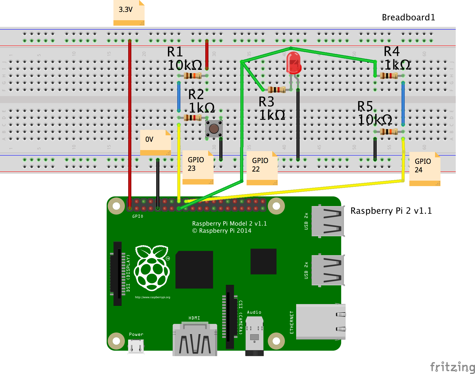
- In the middle we have a LED light which is driven by an output on GPIO pin 22. The otherside of the LED is connected to the ground signal of the Pi. The resistor is needed to limit the current going through the LED; with too high current the LED will break.
-
On the right we have a so called voltage divider circuit which is also driven by an output on GPIO pin 22.
The otherside of the schema is connected to the ground.
The signal between the resistors is read by the GPIO input pin 24 via the yellow line.
- When the output on GPIO pin 22 is low (0V), then no voltage is applied and the voltage level on the yellow line to pin 24 will be 0V. On the Raspberry Pi, 0 Volt is interpreted as a low digital input signal.
- When the output on GPIO pin 22 is high (3.3V) then the resistors R4=1k and R5=10K divide the voltage weighted by their resistance. This means that R4 takes 0.3V and R5 takes 3.0V. Hence, over R4 the voltage will drop with 0.3V from 3.3V to 3.0V. Thus the yellow input line will have voltage 3.0V. On the Raspberry Pi, 3.0 Volt is interpreted as a high digital input signal.
-
On the left we have a similar voltage divider, but this one is always driven by 3.3V from the Pi.
The line connecting the voltage divider to the ground is now controlled by a switch.
- When the switch is not pressed, the circuit is not closed and no current will flow. The signal on the yellow line connected to GPIO pin 23 is high (3.3V).
- When the button is pressed the signal on the yellow line to GPIO pin 23 becomes low (0.3V).
This circuit of point 3 is called a pull-up schema, because in rest - when no button is pressed -
the signal is high.
The circuit of point 2 is called a pull-down schema, because when in rest - when no voltage is applied - the signal is low.
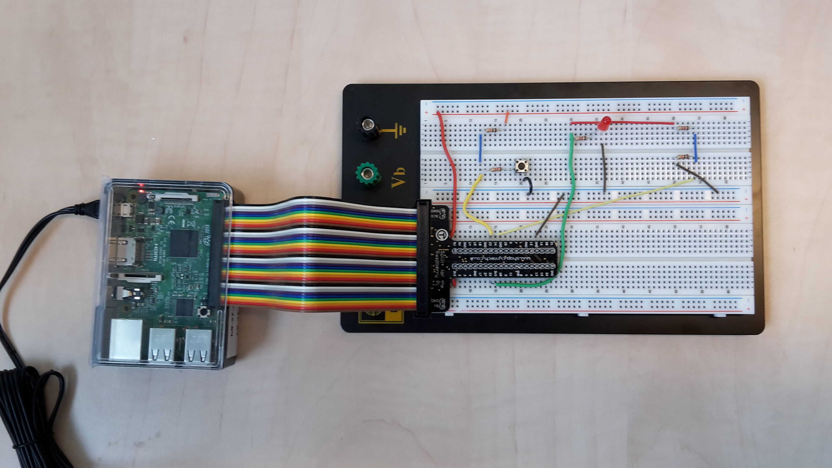
The next photo shows the connection of the GPIO ports of the Rhaspberry Pi to the breadboard using an special flat data cable.
Exercises
Exercise 7a.
Write a program which makes the led blink on and off with a period of 500 milliseconds.Exercise 7b.
Extend the program of 7a such that it counts the interrupts on the yellow line to pin 24. Print the value of the counter after each interrupt.Exercise 7c.
Write a program which counts the interrupts on pin 23 caused by the switch. At each interrupt, toggle the LED on or off and print the value of the counter. Describe and explain the output of the program.Last Updated: 3 June 2019 (Jozef Hooman)
Created by: Harco Kuppens
h.kuppens@cs.ru.nl