A3 H3 The Data Link Layer
The data link layer has to achieve reliable, efficient
communication between two adjacent machines at its level: two
machines physically connected by a communication channel that acts
conceptually like a wire: the bits are delivered in exactly the same
order as they are sent. Limitations to deal with are errors in the
communication circuit, the finite data rate (in wire and computers) and the nonzero
propagation delay between the sending and receiving of a bit.
3.1 Data link layer design issues
 |
The data link layer has to provide a well-defined interface to the
network layer, has to determine how the bits of the physical layer
are grouped into frames to be send as one block, has to deal with
transmission errors and has to regulate the flow of frames, so that
slow receivers are not swamped by fast senders.
|
3.1.1 Services provided to the network layer
Three services are commonly provided:
- Unacknowledged connectionless service.
No attempt is made to
recover lost or corrupted frames at the data link level. Appropriate
when the error rate is very low so recovery is left to higher
layers. Also useful for real-time traffic, like speech or video, in
which late data is worse than bad data.
- Acknowledged connectionless service.
Each frame sent is
individually acknowledged, the sender knows then whether or not a
frame has safely arrived. If the acknowledgment has not arrived
within a specified time interval, it can be sent again, creating of
coarse the possibility of frames that are received more than once.
Useful over unreliable channels, such as wireless systems.
- Acknowledged connection-oriented service.
The source and
destination machines have established a connection before any data
is sent. Each sent frame is numbered and that is used to guaranty
that each frame is received exactly once and in the right order. It
thus provides the network layer with the equivalent of a reliable
bit stream.
Using acknowledgments in the data link layer is a matter of
optimization, never a requirement. The transport layer can always
sent a message and wait for it to be acknowledged or sent the message
again in case of a time-out. If an average message is broken up into
a large number of frames and a sizable fraction of the frames are
lost, a large fraction of the messages must be resend. If messages
are broken up into 10 frames and 1% of the frames are lost then 1% of
the frames must be resent when acknowledgment is used on the data
link level, but 10% of the messages and thus frames must be resent
when acknowledgment is used on the transport level. On reliable
channels, such as fibers, the overhead (in time and resources) of a
heavyweight data link protocol may be unnecessary.
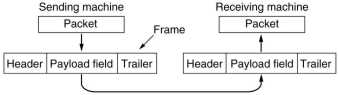
3.1.2 Framing
Data from the transport layer is breaked up into discrete frames
which can be of fixed length, using extra padding bits if needed, or
of variable length but with a maximum size. A checksum is calculated
from the data in the frame and added to it. The receiver recalculates
the checksum and compares it to the send one. If they are not the
same an error has occurred and the receiver has to deal with it.
Breaking up the bit stream into frames is more difficult than it
at first appears. One way is to insert time gaps between frames.
However, networks rarely make any guarantees about timing, thus the
gaps might be squeezed out or extra gaps might be inserted during
transmission. Other methods must thus be used to mark the start and
end of each frame.
 |
A header field can be added to the frame which contains the number
of characters or bits in the frame.
A problem occurs when there is an error in the received count.
Even if the checksum is incorrect so the destination knows the
frame is bad, it has now way to know where the next frame starts.
This method has no way of synchronizing sender and receiver.
Therefore it is rarely used on it self, but always in combination
with the following methods.
|
 |
The next method indicates start and end of frame with special
character sequences, such as the ASCII DLE STX and DLE ETX ( Data
Link Escape, Start of TeXt, End of TeXt). This works good with
text, but with binary data the character sequences may appear in
the data. A way to avoid this, is character stuffing: an extra DLE
is added by the sender before each accidental DLE in the data and
later removed by the receiver.
(What to do with multiple DLE's in the data?)
|
 |
A generalization of this, not connected anymore to ASCII characters,
is bit flagging and stuffing. Each frame begins and ends with a
special pattern of 8 bits: 01111110.
Whenever the sender sees 5 consecutive 1's in the data, it
automatically stuffs a 0 bit into the stream. When the receiver
sees five 1's followed by a 0, it deletes the 0.
The bit handling is done in hardware, so it can be very fast.
|
 |
The stuffing methods were also connected to clock issues: how long is
a bit? Character stuffing was used on simple serial lines with
asynchronous communication. Each character consists of a start
bit, 8 data bits and a stop bit. Even if the clocks of the sender
and receiver differ by as much as 5%, the incoming character can
be correctly sampled.
|
 |
Bit stuffing was used on synchronous lines which used NRZi coding of
data: a 0 is indicated by a change, a 1 by no change in the
voltage level. As there are no more than 5 consecutive 1's, there
is a voltage change at least every 5 bit times. The changes are
used by the receiver to synchronize its clock to the sender. There
is thus no extra clock line needed, the clock is recovered from the data.
|
Some LAN's encode 1 bit of data by 2 physical bits: a 1 bit is
a high-low pair and a 0 bit is a low-high pair. The combinations
high-high and low-low are not used for data, and can be used for
framing.
3.1.3 Error control
Typically the receiver returns special control frames with
positive or negative acknowledgments about the incoming frames. A
negative acknowledgment means that the receiver has received the
frame but found an error in it, the sender has to send it again.
It is possible that a send frame or its acknowledgment is
completely lost, e.g. due to a noise burst. To avoid waiting forever,
the sender starts a timer when sending a frame. When no
acknowledgment arrives before the timer goes off, the sender usually
transmit the frame again. In that case the receiver might receive a
frame twice. To prevent that, it is necessary to assign sequence
numbers to outgoing frames, so that the receiver can distinguish
retransmissions from originals. It also allows for sending frames
when acknowledgment for a previous frame has not yet arrived.
3.1.4 Flow control
Flow control schemes ensures that the sender does not send faster
than the receiver can handle the incoming data. Most contain
well-defined rules about when a sender may transmit the next frame.
Mostly these are based on implicit or explicit permissions from the
receiver.
3.2 Error detection and correction
Errors are still common on analog parts of a communication system
and on wireless transmissions. Errors on some media (e.g. radio) tend
to come in bursts rather than singly. The disadvantage is that burst
errors are harder to detect and correct than isolated errors. An
advantage is that with the same error rate per bit, less frames are
corrupted in case of burst errors than in case of single errors.
3.2.1 Error-correcting codes
Early data communication systems often had error-correcting codes. Later they were seldom used as it
was usually more efficient to use error-detection followed by
retransmission of the not correctly received data.
However with the coming of wireless communication the situation is changing again.
Skip this.
3.2.2 Error-detecting codes
 |
In widespread use is CRC (Cyclic Redundancy Code) also called
polynomial code. A k-bit frame is regarded as the coefficient list
for a polynomial with k terms, ranging from xk-1 to x0,
which is a k-1 degree polynomial. Thus 110001, having 6 bits,
represents a six term polynomial x5+x4+x0.
The sender and receiver must agree upon a generator polynomial
G(x), the high and low order bits thereof must be 1.
The sender
appends r zero bits to the frame, where r is the degree of G(x).
It then divides the bit string corresponding to G(x) into the bits
of the frame. This is done using modulo 2 arithmetic, where
addition and subtraction are equal to XOR. The remainder, which is
r bits or less, is subtracted (modulo 2) from the frame to give
the checksummed frame to be transmitted.
The receiver divides
(modulo 2) the receive frame by G(x), and the remainder should be 0.
To analyze the power of this method, the arriving frame is
written as T(x)+E(x), where T(x) is the sent frame and E(x) is the
error frame having a 1 in each position were the original bit has
been inverted. The receiver computes:
rem{(T(x)+E(x)) / G(x) } = rem {E(x) / G(x)}
Those errors that happen to correspond to polynomials
containing G(x) as a factor will slip by, all others are caught.
Two often used standard CRC's are CRC-16 (x16+x15+x2+1)
and CRC-CCITT (x16+x12+x5+1).
They catch all single and double errors, all errors with an odd
number of bits and all burst errors of length 16 or less.
In hardware CRC's can be easily calculated and checked using a simple
shift register circuit, software is rarely used to calculate CRC's.
|
3.3 Elementary data link protocols
#define MAX_PKT 1024  // packet size
typedef enum {false, true} boolean;
typedef unsigned int seq_nr;
             // sequence or ack number
typedef struct
   {unsigned char data[MAX_PKT];} packet;
typedef enum {data, ack, nak} frame_kind;
typedef struct {
  frame_kind kind; // kind of a frame
  seq_nr seq;   // sequence number
  seq_nr ack;   // acknowledgment number
  packet info;  // network layer packet
} frame; // frames are transported here
// Wait for an event to happen; return type
void wait_for_event (event_type *event);
// Fetch packet from network layer
void from_network_layer(packet *p);
// Put packet to network layer
void to_network_layer(packet *p);
// Get frame from physical layer
void from_physical_layer(frame *r);
// Pass frame to physical layer
void to_physical_layer(frame *s);
// Start the clock, enable timeout event.
void start_timer(seq_nr k);
// Stop the clock, disable timeout event.
void stop_timer(seq_nr k);
// Start auxiliary timer,
//              enable ack_timeout event
void start_ack_timer(void);
// Stop auxiliary timer
//              disable ack_timeout event
void stop_ack_timer(void);
// Allow network layer to cause a
//           network-layer-ready event.
void enable_network_layer(void);
// Forbid network layer from causing a
//           network-layer-ready event.
void disable_network_layer(void);
// Macro inc is expanded in-line
//   Increment k circularly.
#define inc(k)
      if (k < MAX_SEQ) k=k+1; else k=0

Fig. 3-9. definitions needed in protocols
|
We assume that the physical, data link and network layers are
independent processes that communicate by passing messages back
and forth. They might run on different processors: main CPU, CPU
on I/O card or a special purpose network chip. Another assumption
is that machine A wants to send a long stream of data to machine B
using a reliable, connection-oriented service. A packet received
from the network layer of machine A will be passed unchanged to the network layer
of machine B, no physical or data link headers or trailers
remain added. The packets are all of the same length to keep it simple.
The data link layer is waiting for something to happen (a
message from the other layers, timer timeouts) by calling a
function, which returns only when something has happened. In
practice usually interrupts are used, but for simplicity only
busy-waiting will be considered. Communication to and from the
physical and network layer is done by calling library functions.
A frame consists of 3 frame header fields and the data field,
consisting of a single packet. The kind field tells which kind of
frame it is, a normal data frame or a frame special to the data
link protocol, e.g. an acknowledgment frame.
Sequence and acknowledgment numbers are small integers in the
range 0 to MAX_SEQ, used by the protocol to number frames and
acknowledgments in order to tell them apart.
The macro inc() is used to increment a sequence number by 1
circularly, as this is frequently needed. |
3.3.1 An unrestricted simplex protocol
// Protocol 1 (utopia)
typedef enum {frame_arrival} event-type;
#include "protocol.h"

void sender1 (void)
  frame s;       // an outbound frame
  packet buffer; // an outbound packet
  while (true) (
    from_network_layer(&buffer);
                      // get packet
    s.info = buffer; // copy it to frame
    to-physical-layer(&s); // send it
  }
}

void receiver1(void)
  frame r;
  event_type event;
       // filled by wait, not used here
  while (true) {
    wait_for_event(&event);
      // only possibility is frame-arrival
   from_physical_layer(&r); // get frame
   to_network_layer(&r.info);
       // pass data to networklayer
  }
}
Fig. 3-10. An unrestricted simplex protocol.
|
Protocol1 (utopia) provides for data transmission in one direction only,
from sender to receiver. The communication channel is assumed to
be error free, and the receiver is assumed to be able to process
all the input infinitely fast and is not limited by buffer space.
Consequently, the sender just sits in a loop pumping data out
onto the line as fast as it can. The receiver sits also in a loop
waiting for a frame to arrive, then reads the frame and passes the
data portion of it on to the network layer.
In JAVA sender1() and receiver1() would be implemented as threads. |
3.3.2 A simplex stop-and wait protocol
//Protocol 2 (stop-and-wait)

typedef enum {frame-arrival} event_type;
#include "protocol.h"

void sender2(void){
  frame s;           // buffer for frame
  packet buffer;   // buffer for packet
  event_type event;  // frame_arrival only
  while (true) {
    from_network_layer(&buffer); // get packet
    s.info = buffer;        // copy it into frame
    to_physical_layer(&s);  // send it
    wait_for_event(&event); // wait for ack
  }
}

void receiver2(void) {
  frame r, s;        // buffers for frames
  event_type event;  // frame-arrival only
  while (true) {
    wait_for_event(&event);  // wait for frame
    from_physical_layer(&r);  // get frame
    to_network_layer(&r.info); // pass data
    to_physical_layer(&s);
      // send a dummy frame to awake sender
  }
}
Fig. 3-11. simplex stop-and-wait protocol
|
Protocol 2 (stop-and-wait) also provides for a one-directional flow of data
from sender to receiver. The communication channel is once again
assumed to be error free, as in protocol 1. However, this time,
the receiver has only a finite buffer capacity and a finite
processing speed, so the protocol must explicitly prevent the
sender from flooding the receiver with data faster than it can be handled.
After sending a frame the sender waits now an acknowledgment
frame which is send by the receiver after it has received the
frame and passed the data in it to its network layer.
The content of the acknowledgment frame is not important, only
the fact that it has arrived. In practice the acknowledgment frame
would be made as small as possible. |
3.3.3 A simplex protocol for a noisy channel
// Protocol 3 (par)
#define MAX_SEQ 1 // must be 1 for protocol 3
typedef enum {frame_arrival,
     cksum_err, timeout} eventtype;
#include "protocol.h"

void sender3(void) {
 seq_nr next_frame_to_send;
      // seq number of next outgoing frame
 frame s;             // scratch variable
 packet buffer;   // buffer for outbound packet
 eventtype event;
 next_frame_to_send = 0;   // initialize

 from_network_layer(&buffer);// get first pkt
 while (true) {
  s.info = buffer; // construct outgoing frame
  s.seq = next_frame_to_send; // insert seq nr
  to_physical_layer(&s); // send it away
  start_timer(s.seq);
     // if answer takes too long: timeout
  wait_for_event(&event);
     // frame-arrival, cksum_err, timeout
  if (event == frame-arrival) {
!   from_physical_layer(&s); // get ack
!   if (s.ack == next_frame_to_send) {
     from_network_layer(&buffer);
                  // get next one to send
     inc(next_frame_to_send);  // invert seq nr
!   }
  }
 }
}

void receiver3(void) {
 seq_nr frame_expected;
 frame r, s;
 event_type event;

 frame_expected = 0;
 while (true) {
  wait_for_event(&event);
              // frame-arrival, cksum-err
  if (event == frame_arrival) {//valid frame
   from_physical_layer(&r);   // get it
   if (r.seq == frame_expected){
      // this is what we have been waiting for
    to_network_layer(&r.info);
                   // data to networklayer
    inc(frame_expected);
     // next time expect the other sequence nr
   }
!   s.ack = 1 - frame_expected;
                // tell which frame is acked
   to_physical_layer(&s);
         // none of the other fields are used
  }
 }
}
|
The communication channel is unreliable, frames may be damaged or lost
completely. Checksums are used to detect faulty packets. If the
frame is corrupted in such a way that the checksum is nevertheless
correct, this protocol (and all other protocols) fails: it delivers
an incorrect packet to the network layer.
One might think that a variation of protocol 2 would work:
adding a timer to the sender. The receiver sends only an ack frame
for a correctly received frame. As no ack is send for a damaged
frame, the sender would timeout and retransmit the frame. What is
the problem with this protocol?
The ack frame could also be lost completely. A frame would then
be send twice and as the receiver has no way to distinguish them,
the data in them would be passed to the network layer. If A is
sending a file to B, part of the file will be duplicated.
The receiver must thus be able to distinguish a frame from its
retransmission. The obvious way to achieve this is to have the
sender put a sequence number in the header of each frame it sends.
A 1 bit sequence number is enough for this, the order of sequence
numbers of send frames is thus normally 0,1,0,1, etc. A
retransmitted frame has the same sequence number as the original
one. The receiver remembers the sequence number of the last frame
received correctly, if the next frame has the same sequence number
it must be a retransmission due to a not received ack. It is then
not send to the network layer, only an ack is send back to let the
sender know that the frame has arrived.
The protocol, as given in a previous version of the book, still
had a problem. What happens when the timeout interval is not long
enough? The sender may then retransmit while the ack of the
previous frame is still on its way (in receiver3(), in its
physical layer, on the wire or in the physical layer of the
sender). That ack is then regarded as the ack of the retransmitted
frame and the sender sends the next frame while the ack of the
retransmitted frame is still under way. There is thus an extra ack
in the system, which will eventually acknowledge a lost or damage
data frame, which is then not retransmitted.
To prevent this problem the ack frame must contain information
on which data frame it acknowledges, the sequence number of the
data frame can be used for that. The lines flagged with !
were thus added to the protocol. If the receiver receives an ack
which is not for the last frame send, it retransmit the frame. |
Protocols in which the sender waits for a positive ack before
going to the next data item, like the ones described above, are
called PAR (Positive Acknowledgment with Retransmission) or ARQ
(Automatic Repeat reQuest).
Note that an optimal setting of the timeout interval is important
in this protocol, and in all protocols which use timeout. If the
interval is too short unneeded retransmissions occur, if it is too
long bandwidth is wasted as the sender waits too long before doing a
retransmission. Often implementations of protocols measure the round
trip time (time between sending data to the lower layer and receiving
the ack) and use an algorithm to change the timeout interval. In
lower layers the variation in round trip times is usually smaller
than in higher layers, making the algorithms for the higher layers
often very complex, like the one usually used for TCP.
3.4 Sliding window protocol
We will now consider situations in which data must be send in both
directions. An acknowledgment can now be attached to an outgoing data
frame by using the ack field in the frame header, instead of being
sent as a separate frame, this is called piggybacking. This gives a
better use of the available channel bandwidth as it costs only a few
bits of the ack field instead of a separate frame with header, ack
field and checksum. Fewer frames means also fewer "frame
arrived" interrupts and perhaps fewer buffers in the receiver.
One should however not wait too long for an outgoing data frame to
piggyback the ack on, thus some timeout must be used to detect that
situation and then send a separate ack frame instead.
When the round trip time is long, waiting for an ack to send the
next frame can eat up a large part of the available bandwidth.
Consider a 64 Kbps N-ISDN connection from here to New York, say 5000
km away. Sending a 1280 bit frame takes then 20 ms, supposing it
travels at 2/3 the speed of light it takes 25 ms for a bit to arrive
in New York. After 45 ms the frame is fully in New York, a short ack
frame can at the earliest be back 70 ms after the sender starts
sending the frame, not counting processing time at sender and
receiver. Thus 50 out of 70 ms, about 70% of the time the sender is
doing nothing. The combination of long transit time, high bandwidth
and short frame length is disastrous in terms of efficiency.
The solution is sending new frames before ack's from the previous
ones have arrived. In the so-called sliding window protocols each
sent frame contains a sequence number, ranging from 0 to a maximum,
usually 2n-1. The sender maintains a set of sequence
numbers, which it is permitted to send. These frames are said to fall
within the "sending window" denoted by a lower and higher
bound. As more than 1 frame can be on its way on the communication
channel, this technique is also known as pipelining.
The sender must keep a send frame in a buffer until its ack is
received. If the sending window grows to its maximum size, no more
packets must be accepted from the network layer.
There are two basic approaches for the receiver to handle errors
in frames. One is to accept only a frame with the next expected
sequence number, discarding all further send frames. This is called
"go back n" as the sender might have to retransmit up to n
frames (with n its maximum window size). The other approach is to
accept following frames and let the sender only retransmit the lost
or damaged frame: "selective repeat". The receiver must
thus maintain a "receiving window" of sequence numbers it
is allowed to receive. ( In case of "go back n" one can
speak of a receiving window of size 1.)
If the receiver window is larger than 1, frames could be received
out of order e.g. if sequence number 0 is lost or damaged and 1
arrives correctly. But its network layer must be fed in the right
order, thus the receiver data layer should also be able to store
frames.
The sending and receiving windows don't need to have the same
size, in some protocols sizes are fixed, in others they can grow or
shrink as frames are sent and received.
3.4.1 A one-bit sliding window protocol
// Protocol 4 (1-bit sliding window)

#define MAX_SEQ 1        // must be 1 for protocol 4
typedef enum (frame_arrival,
    cksum_err, timeout) event-type;
#include "protocol.h"

void protocol4 (void) {
 seq_nr next_frame_to_send; // 0 or 1 only
 seq_nr frame_expected;    // 0 or 1 only
 frame r, s;            // scratch variables
 packet buffer;         // current packet being sent
 event_type event;
 next_frame_to_send = 0;
 frame_expected = 0;    // expected nr of arriving fr

 from_network_layer(&buffer); // fetch pkt
 s.info = buffer;            // prepare to send initial frame
 s.seq = next_frame_to_send; // insert seq nr into frame
 s.ack = 1 - frame_expected; // piggybacked ack
! to_physical_layer(&s);       // transmit the frame
! start_timer(s.seq);          // start the timer running
 while (true) {
  wait_for_event(&event);     // frame-arrival,
                              //     cksum-err, or timeout
  if (event == frame_arrival) { // frame arrived undamaged.
   from_physical_layer(&r);     // go get it
   if (r.seq == frame_expected) { // Handle it.
     to_network_layer(&r.info); // pass pkt to network layer
     inc(frame_expected);      // invert seq nr expected next
   }
   if (r.ack == next_frame_to_send) {// handle outbound fr
     from_network_layer(&buffer);// get new pkt
     inc(next_frame_to_send);    // invert sender's seq nr
   }
  }
  s.info = buffer;              // construct outbound frame
  s.seq = next_frame_to_send;   // insert seq nr into it
  s.ack = 1 - frame_expected;   // seq nr last received fr
  to_physical_layer(&s);    // transmit a frame
  start_timer(s.seq);           // start the timer running
 }
}
Fig. 3-14. A 1-bit sliding window protocol.
|
As the maximum window size is 1, this is still a stop-and-wait protocol.
Normally one of the two data link layers should start first
with sending while the other should wait for a frame to arrive.
Thus the lines denoted by ! should be
skipped by one of the sides.
If that is not the case, the protocol still works but at least
half of the frames are retransmissions, see fig. 3-15. Similar
situations can occur as result of a premature timeout.
Ack's are always send piggybacked, so we assume that there is a
high packet rate in both directions. |
3.4.2 A protocol using go back n
This protocol 5 as given in fig. 3-17 allows the sender to
transmit up to MAX_SEQ frames without waiting for an ack. It does not
assume that the network layer has always a new packet available, but
lets it generate a network_layer_ready event when there is a packet.
This also used to avoid the problem of protocol 4: who starts first?
Note that there are MAX_SEQ+1 possible distinct sequence numbers,
but only a maximum of MAX_SEQ outstanding, not acked frames, which
need to be buffered in case retransmission is needed. Also a separate
timer is needed for each outstanding frame. These can be easily
simulated in software, using a single hardware clock that causes
interrupts periodically, see fig. 3-18.
If the sender buffers are full, the network layer is prohibited to
generate another event, otherwise it is enabled to do so. In fact in
the code the call disable_network_layer() is not needed, why?
Ack's are always piggybacked. The receiver might have accepted and
passed to its network layer many (how much?) frames before it has the
chance to send an ack back. It then ackes the last received frame.
For the sender this means that an ack of frame n implies the ack's of
lower sequence numbers.
3.4.3 A protocol using selective repeat
// Protocol 6 (nonsequential receive)
#define MAX_SEQ 7                     // should be 2^n - 1
#define NR_BUFS ((MAX_SEQ + 1)/2)
typedef enum {frame_arrival, cksum_err, timeout,
              network_layer_ready, ack_timeout} event_type;
#include "protocol.h"
boolean no_nak = true;    // no nak has been sent yet
seq_nr oldest_frame = MAX_SEQ + 1;
                    // initial value is only for the simulator

static boolean between(seq_nr a, seq_nr b, seq_nr c) {
 return ((a <= b) && (b < c)) || ((c < a) && (a <= b)) ||
            ((b < c) && (c < a));
}

static void send_frame(frame_kind fk, seq_nr frame_nr,
                    seq_nr fr_expected, packet buffer[]) {
              // Construct and send a data, ack, or nak frame.
 frame s;      // scratch variable
 s.kind fk;   // kind == data, ack, or nak
 if (fk == data) s.info = buffer[frame_nr % NR_BUFS];
 s.seq = frame_nr;   // only meaningful for data frames
 s.ack = (fr_expected + MAX_SEQ) % (MAX_SEQ + 1);
 if (fk == nak) no_nak = false;  // one nak per frame, please
 to_physical_layer(&s);     // transmit the frame
 if (fk == data) start_timer(frame_nr % NR_BUFS);
 stop_ack_timer();         // no need for separate ack frame
}

void protocol6(void) {
 seq_nr ack_expected = 0;   // lower edge sender window
 seq_nr next_fr_to_send = 0; // its upper edge + 1
 seq_nr fr_expected = 0;  // lower edge receiver window
 seq_nr too_far = NR_BUFS; // its upper edge + 1
 int i;                    // index into buffer pool
 frame r;                  // scratch variable
 packet out_buf[NR_BUFS];  // buffers for sending
 packet in_buf[NR_BUFS];   // buffers for receiving
 boolean arrived[NR_BUFS]; // inbound bit map
 seq_nr nbuffered = 0;  // nr of output buffers in use
 event_type event;

 enable_network_layer();   // initialize
 for (i = 0; i < NR_BUFS; i++) arrived[i] = false;
 while (true) {
  wait_for_event(&event);  // five possibilities
  switch(event) {
   case network_layer_ready: // get, save,transmit new fr
    nbuffered = nbuffered + 1;  // expand the window
    from_network_layer
           (&out_buf[next_fr_to_send % NR_BUFS]);
    send_frame(data, next_fr_to_send, fr_expected, out_buf);
    inc(next_fr_to_send);      // advance upper window edge
    break;
   case frame_arrival:      // a data or control frame arrived
    from_physical_layer(&r);
    if (r.kind == data) { // An undamaged data frame arrived.
     if ((r.seq != fr_expected) && no_nak) // frame lost?
       send_frame(nak, 0, fr_expected, out_buf); // send nak
     else start_ack_timer();
     if (between(fr_expected, r.seq, too_far) &&
        (arrived[r.seq % NR_BUFS] == false)) {
             // Frames may be accepted in any order.
      arrived[r.seq % NR_BUFS] = true; // mark buffer as full
      in_buf[r.seq % NR_BUFS] = r.info;   // insert data
      while (arrived[fr_expected % NR_BUFS]) {
         // Pass frames to network layer and advance window.
       to_network_layer(&in_buf[fr_expected % NR_BUFS]);
       no_nak = true;
       arrived[fr_expected % NR_BUFS] = false;
       inc(fr_expected); // incr lower edge of receiver window
       inc(too_far);     // incr upper edge of receiver window
       start_ack_timer(); // to see if separate ack is needed
      }
     }
    }
    if((r.kind==nak) && between(ack_expected,
          (r.ack+l) % (MAX_SEQ+1),next_fr_to_send))
      send_frame(data, (r.ack+1) % (MAX_SEQ+1),
                   frame_expected, out_buf); // resend
// Should not an "else" be placed here for r.kind == ack
    while (between(ack_expected, r.ack, next_fr_to_send)) {
      nbuffered = nbuffered - 1;    // handle piggybacked ack
      stop_timer(ack_expected % NR_BUFS); // fr arrived intact
      inc(ack_expected);   // inc lower edge of sender window
    }
    break;
   case cksum_err:  // damaged frame, send nak
    if (no_nak) send_frame(nak, 0, fr_expected, out_buf);
    break;
   case timeout: // we time out
    send_frame(data, oldest_frame, fr_expected, out_buf);
    break;
   case ack_timeout: // ack timer expired;
    send_frame(ack,0,fr_expected, out_buf); // send ack
    if (nbuffered < NR_BUFS) enable_network_layer();
    else disable_network_layer();
  }
 } // end infinite while() loop
}
Fig. 3_19. A sliding window protocol using selective repeat.
|
The receiver accepts frames out of order, but has to pass packets to
the network layer in order.
The sender window grows and shrinks between 0 and a maximum
value, the receiver window is equal to that maximum value:
NR_BUFS.
It can be shown that NR_BUFS should be less or equal to half
the number of available sequence numbers. Otherwise it can go
wrong in a particular situation (see fig. 3-20): the sender has transmitted its
maximum number of frames, the receiver has accepted them and
passed to its network layer, but all the ack's have been lost.
The number of buffers for both the sender and receiver are
equal to NR_BUFS. The sender has a timer on each of its buffers.
In this protocol, in contrast to protocol 5, it is difficult to
determine which frame has timed out. We assume here that the timer
administration finds that out and sets a global variable:
oldest_frame.
Ack's are piggybacked, but if the receiver has to wait too long
before it can send the ack, it sends a separate ack frame. For
this an ack_timer is used. It is important that its timeout
interval is shorter than the interval used for timing out data
frames. This makes sure that an ack arrives before the sender
starts retransmitting.
When the receiver thinks that an error has occurred (a damaged
frame or a frame other than the expected one arrives, indicating a
potential lost frame) it sends back a so-called negative
acknowledgment frame (nak frame). The sender can then retransmit
the frame indicated by the nak immediately instead of waiting for
the timeout of that frame. The receiver makes sure that it sends
only one nak for a given frame (why?).
Nak's are useful when the variations in round-trip time are
large. The retransmission timeout interval must then be set at a
large value, to avoid too many retransmissions, thus the nak's can
speed up retransmission of lost or damaged frames. |
3.5 Protocol specification and verification
As we have seen realistic protocols and their implementations are
quite complicated. Much research has been done to find formal methods
to specify and to verify protocols and implementations. This is
getting even more important now that many protocols get implemented
in embedded CPU's or in special purpose chips.
As this subject is treated in the PV course, we will not treat it
here.
3.6 Example data link protocols
We will look only at the PPP protocol.
 |
This is used to connect a user machine at home to an Internet provider
or to a university or company allowing access to their machines by
students or employees. The connection can be via an analog
telephone line or via N-ISDN.
PPP (Point to Point Protocol) provides 3 things. A framing
method that delineates start and end of frames and provides error
detection. The LCP (Link Control Protocol) to bring lines up and
testing them, to negotiate options, and to gracefully bring down
connections. The NCP (Network Control Protocol) to negotiate
network layer options in a way that is independent of the network
layer protocol to be used.
|
 |
When the line is DEAD, no physical layer carrier is present and no
connection exists. After physical connection is established, the
phase moves to established. Then LCP option negotiation begins,
which, if successful, leads to AUTHENTICATE to check each other's
identities. When the NETWORK phase is entered, the NCP is used to
configure the network layer. If that is successful, OPEN is
reached and data transport can take place. At the end of that NCP
and LCP care for a good termination of the connection.
|
The frame format uses the standard HDLC flags to delineate
frames. But instead of bit stuffing, character stuffing is used,
so all frames are an integral number of bytes. The Address field
is always all 1's.
The Control field indicates default an unnumbered frame, thus
no seq numbers and ack's are used. But it can be negotiated to use them.
As Address and Control fields are constant in the default
configuration, LCP can be used to negotiate to omit them, saving 2
bytes per frame.
The Protocol field tells which packet (LCP, NCP, IP, IPX, etc.)
is in the payload, default it is 2 bytes but it can be negotiated
down to 1 byte.
The Payload field is of variable length (in bytes), up to some
negotiated maximum, default is 1500 bytes. The checksum is
normally 2 bytes, but 4 bytes can be negotiated.
Gewijzigd op 28 januari 2003 Theo
Schouten.