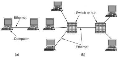
In any broadcast network, a key issue is how to determine who gets to use the communication channel when there is competition for it. Broadcast channels are therefore sometimes called multi-access or random access channels. The access protocols belong to a sublayer of the data link layer, called the MAC (Medium Access Control) sublayer.
The traditional way of allocating a channel among multiple competing users is FDM: if there are N users, the bandwidth is divided into N equal sized partitions. If the number of users is fixed and each has a heavy (buffered) load (e.g. switching offices of telephone companies) FDM is a simple and efficient allocation strategy. If however the number of users vary problems arise. If fewer than N users want to communicate, part of the available bandwidth is not used. If there are more than N users, some of them can not be served, even if some of the served users hardly transmit or receive anything. Even if the number of users is somehow kept constant, bandwidth can be wasted because data traffic is often bursty, peak to mean traffic ratio's of 1000:1 are quite common. These problems also apply to TDM.
Some queuing theory calculations to show the inefficiency of FDM.
Suppose a channel with a capacity of C bps, frames arriving according
a Poisson distribution with a mean of
![]() frames/sec, each having a length drawn from an exponential pdf
(probability density function) with mean 1/
frames/sec, each having a length drawn from an exponential pdf
(probability density function) with mean 1/![]() bits/frame. The mean time T a packet has to wait before it can be
send is then: T = 1 / (
bits/frame. The mean time T a packet has to wait before it can be
send is then: T = 1 / (![]() C -
C -![]() ). Now the channel is divided into N independent channels with
capacity C/N bps, the mean input rate for each of the subchannels is then
). Now the channel is divided into N independent channels with
capacity C/N bps, the mean input rate for each of the subchannels is then
![]() /N. Then TFDM = 1 / (
/N. Then TFDM = 1 / (![]() (C/N) -(
(C/N) -(![]() /N)
) = N/ (
/N)
) = N/ (![]() C -
C -![]() ) = NT. The mean time delay for a packet to be send using FDM is thus
N times worse than if all the frames were somehow magically arranged
orderly in a big central queue.
) = NT. The mean time delay for a packet to be send using FDM is thus
N times worse than if all the frames were somehow magically arranged
orderly in a big central queue.
Several assumptions are used in dynamic channel allocation.
Station model. There are N independent stations, each with
a program or user that generates frames for transmission. Usually the
pdf of frame generation is taken to be a poisson distribution with
mean
![]() frames/sec.
The size of a frame is either constant or from an exponential
distribution.
frames/sec.
The size of a frame is either constant or from an exponential
distribution.
Single channel. A single channel is available, all stations can transmit on it and receive from it. As far as the hardware is concerned all stations are equal, although protocol software may assign priorities to them.
Collision. If two frames are transmitted simultaneously, the resulting signal is garbled. All stations can detect collisions.
Time. With continuous time, frame transmission can begin at any instant. With slotted time, time is divided into discrete intervals called slots, frame transmission always begin at the start of a slot. A slot may contain 0 (idle), 1 (successful transmission) or more (a collision) frames.
Carrier sense. Stations can either tell if the channel is in use or not. If they can, they do not send when the carrier is in use. If they can not, they just go ahead and send. LAN's usually have carrier sense possibilities.
ALOHA, devised in the 1970's, used ground based radio broadcasting, its MAC protocol provided basic idea's applicable to many broadcast systems.
In pure ALOHA users transmitted whenever they had data to send. There will be of course collisions and the colliding frames are corrupted. However, due to the feedback property of broadcasting, a sender can always find out whether or not its frame was destroyed by listening to the channel, the same way other users do. If the frame was destroyed, the sender just waits a random amount of time and sends again. The waiting time must be random or the same frames will collide over and over, in lockstep.
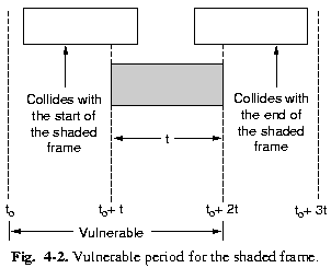 |
Let the "frame time" denote the amount of time to send the standard, fixed length frame. Assume that new frames are generated (by an infinite number of stations) according a Poisson pdf with mean S frames per frame time. Assume further that the pdf of transmissions (new frames and retransmissions) is also Poisson with mean G. Then S=GP0 with P0 the probability that a frame does not suffer a collision. Look at the shaded frame, if the other stations do not start sending a frame during its frame time and the previous frame time, there will be no collision. The probability that k frames are send in 2 frame times is: Pr[k] = ( (2G)k e-2G )/ k!. The probability of 0 frames, meaning no collision, is thus P0=e-2G. Thus S=Ge-2G |
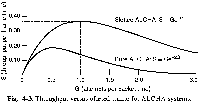 |
The maximum throughput S per frame time, occurs at G=0.5, giving S = 1/2e = 0.184, thus a channel utilization of only 18%. In slotted ALOHA, stations only transmit at the beginning of a slot, which has the length of a frame time. Thus if a station has something to send, it waits until the beginning of the next slot. A possibility to determine the beginning of slots, would be to have one special station which emits a short signal. The vulnerable period is now reduced to 1 frame time, thus S=Ge-G. The maximum throughput S is now 37%. |
Persistent and Nonpersistent CSMA
In 1-persistent CSMA, if a station has data to send, it
first listen to the channel to see if someone else is transmitting at
that moment. If not, it starts transmitting, else it keeps listening
until the channel becomes free. If a collision occurs, the station
waits a random amount of time and than starts listening to the
channel again. This protocol is called 1-persistent because a station
transmits with probability 1 whenever it finds the channel idle.
The
propagation delay is important for the performance. If a station
starts sending, another station might sense the channel before the
signal of the first station reaches it, thus it detects an idle
channel and starts transmitting also, generating a collision. The
longer the propagation delay (longer cable, larger distance between
stations using radio), the more important this effect becomes.
Even
if the propagation delay is 0, two stations might wait politely until
the third one is finished and then start sending at the same time,
generating a collision.
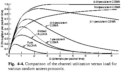
In non-persistent CSMA the stations are not so greedy. If a station detects that the channel is occupied, it waits a random amount of time before it looks again to the channel. Intuitively this will lead to a better channel utilization, but also to longer wait times for a station (specially when the load is low), than 1-persistent CSMA.
With slotted channels also p-persistent CSMA can be used. When a station is ready to send, it senses the channel. If it is idle, it transmits with a probability of p. With a probability q=1-p it defers to the next slot. If that slot is idle, it either transmit or defers again with probabilities p and q. This is repeated until either the frame has been send or another station has begun transmitting. In the latter case it acts as there has been a collision, it waits a random time and starts again. If the station initially senses the channel busy, it waits until the next slot and applies the above algorithm.
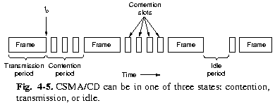
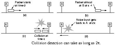
Here stations abort their transmissions as soon as they detect a collision. After a transmission is finished at point t0, any other station having something to send may now attempt to do so. If two or more stations decide to do so, a collision occurs.
This can be detected by a station by looking at the power or
pulse width of the received signal and comparing it with the send
signal. This is an analog process, the stations hardware must be
able to listen to the cable while it is transmitting. The signal
encoding must be so, that a collision changes the send signal
significantly (e.g. a collision of two 0 volt signals is
impossible to detect).
The maximum time before a collision is
detected is twice the propagation delay in the cable. After a
collision has been detected, the involved stations abort their
transmissions and wait a random amount of time before looking to
the cable again.
CSMA/CD is an important protocol, it is used in Ethernet (IEEE 802.3).
In this discussion we assume that all radio transmitters have some fixed range. In reality there is an volume where the signal is usable by a receiver, outside that in adds to the noise perceived by a receiver making receiving of other senders more error prone. Walls and other objects may also cause reflection of a signal leading to delayed signals and interference with the directly received signal.
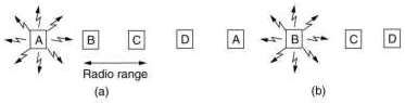
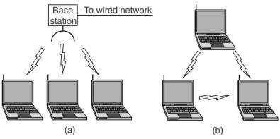
A difference with a wired LAN is that not all stations are within range of each other. This makes CSMA on its self not usable. In (a) C can not sense that A is sending, so when it starts sending it causes a collision at B. This is the hidden station problem. In (b) B wants to transmit to A. Now C senses that B is sending, but it can still send to D. This is the exposed station problem. For a station that wants to send, needs information about the situation around the receiving stations.
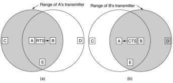
An early (1990) protocol is MACA (Multiple Access with Collision Avoidance). If A wants to send to B it first sends a RTS (Request To Send)frame to B, this small frame contains the length of the data frame A wants to send. The B replies with a CTS (Clear To Send) frame, causing A to send its data. Any other station hearing the RTS, like C, remains silent long enough for the CTS to be received by A. Any other station hearing the CTS, like D, remains silent long enough for the data frame to be received by B. A and B must have sufficient information for their wait time, thus both RTS and CTS contain the length of the data frame, besides the identification of sending and receiving station.
Collisions still can occur, like B and C both sending a RTS frame to A at the same time. These will collide and A does not detect a valid frame. B and C do not receive a CTS frame within the expected time. They conclude that there is a problem and they wait a random time before trying again. This according the binary exponential backoff algorithm, explained in 4.3.
MACAW (W for wireless) is an improvement. They added a returned ACK frame after the data frame is correctly received. The backoff algorithm is run for each source-destination pair separately rather than for each station. CSMA is used to keep a station from transmitting a RTS to another station if it senses that a nearby station is already doing that.
The IEEE802 standards are divided into parts. The 802.1 standard gives an introduction and defines the interface primitives. The 802.2 standard describes the upper part of the data link layer, which uses the LLC (Logical Link Control) protocol. Parts 802.3 trough 802.5 define the CSMA/CA (better known as Ethernet), token bus and token ring LAN standards, each covering the physical layer and MAC sublayer protocols.
Later came 802.11 (wireless LAN), 802.15 (Bluetooth) and 802.16 (wireless MAN). Although the physical layer and MAC sublayer are different, all 802.x have the same logical link sublayer (802.2). Thus the interface to the network layer is the same.
Ethernet was the name given by XEROX to its 3 Mbps CSMA/CD system, later speeded up to 10 Mbps. It differs only slightly from IEEE 802.3. Therefore the name "Ethernet" is generally used for IEEE 802.3 networks and even sometimes for all CSMA/CD networks.
| Name | Cable | Max. segment | Nodes/seg | Interface | Advantages |
| 10Base5 | Thick coax | 500 m | 100 | vampire transceiver | Good for backbones |
| 10Base2 | Thin coax | 200 m | 30 | BNC-T junction | Cheapest system |
| 10Base-T | Twisted pair | 100 m | 1024 | Hub | Easy maintenance |
| 10Base-F | Fiber | x2000 m | x1024 | Best between buildings |
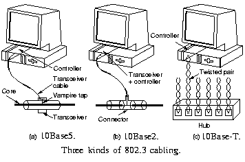 |
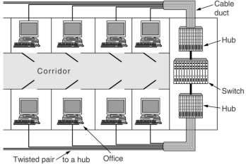
Why is the number of nodes per segment limited? With coax cable bad taps, loose connectors, faulty transceivers and controllers, and cable breaks are difficult to find. Time domain reflectrometry can be used to find them. A pulse of known shape is generated on one end of the cable. Distortions in impedance and the end of the cable will generate echo's, which can be timed to determine their positions. The hub contains electronics to arrange the connected UTP cables into a logical bus. Adding and removing cables is easy, cable breaks can be easily detected. |
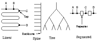 |
With spine and tree topologies, the junctions must contains boxes to match the impedance. But often repeaters are used, which receive, amplify and retransmit signals in both directions. Repeaters must be used if the maximum segment length is reached. A system may contain multiple cable segments and repeaters but no 2 receivers may be more than 2.5 km apart or have more than 4 repeaters between them (repeaters add time delay). |
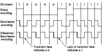 |
Ethernet uses manchester encoding with +0.85 V for the high and -0.85 V for the low signal. If no station is sending the voltage is 0. No external clock signal is needed, as each bit contains a voltage swing. A high-to-low voltage denotes a "1", a low-to-high voltage a "1". |
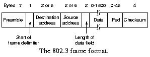 |
Each frame starts with 7 bytes, each containing 10101010, generating a
10 MHz square wave for 5.6 µsec. This allows the receiver's
clock to synchronize with the sender's clock. |
The address containing all 1's is reserved for broadcast. Bit 46 (adjacent to the high-order bit) is used to distinguish local from global addresses. Global addresses are assigned by IEEE to ensure that no 2 stations anywhere in the world have the same global address, with 48-2=46 bits available there are about 7 1013 global addresses.
 |
The length of the data field can be from 0 to 1500, but padding must be used to ensure a minimum frame length of 64 bytes. When B detects a collision, it aborts sending its frame and sends out a 48 bit noise burst. A must detect this before it is ready with sending, otherwise it thinks that its frame was sent correctly. |
All frames must thus be longer than the maximum round trip time (on a 2500 m cable with 4 repeaters), which amounts to 64 bytes. This also makes it easier to distinguish valid frames from stray bits and pieces of frames on the cable due to an abortion.
A binary exponential backoff algorithm is used to randomize retries after a collision. Time is divided up into slots of 51.2 µs, twice the maximum round trip time. After the first collision, each station waits 0 or 1 slot times before trying again. If 2 stations collide and they choose the same random number (a probability of 0.5), the second collision occurs. Then a random number between 0 and 3 is chosen, the probability of a third collision is then 0.25. In general after i collision a random number between 0 and 2i-1 is chosen, up to a maximum of 1023. This algorithm ensures a low delay when only a few stations collide, but also that the collision is resolved in a reasonable interval when many stations collide.
A lot of theoretical analysis of the performance of 802.3 has been done. Virtually all of them assume Poisson distribution of offered packets and in the beginning also used approximations for the random wait algorithm. Only recently researchers started to check the Poisson assumption and found that real traffic is rarely Poisson, but self-similar. That means that averaging over long periods of time does not smooth out the traffic. The average number of packets in each minute of an hour has as much variance as the average number of packets in each second of a minute.
The network efficiency increases with longer frame lengths (the transmission period is then long compared to the contention period) and with less stations trying to send (the contention period gets smaller then). Good higher level protocols (like piggybacking ack's and nak's) can help with both.
 |
A switch can be used the reduce the number of stations competing to send. Its checks an incoming frame to see if it addresses a station on the other cable. If so, it makes the connection to the other cable, otherwise not. It introduces thus a delay of a bit more than 14 bytes. Other kind of switches store incoming frames, destinated to the other input port, in RAM before trying to send them to that port. Each cable then becomes a separate collision domain with 4 stations on it, instead of a single collision domain with 6 stations. The switch becomes more effective if the traffic between the domains is smaller than the traffic inside domains. |
Ethernet has been around for a long time. In our faculty since the beginning of the eighties the thick yellow cable connected the mainframe (IBM) and mini computers (VAX with VMS, VAX and SUN with Unix). With the coming of the personal computer the thin cable was used to connect them to the mini's, now called server. The Apple computers used first Appletalk and then Ethernet, both TCP/IP and Appletalk protocol over them.
For needed higher than 10 Mbps optical LAN's and ATM were used. They were used as backbone networks, neither made the breakthrough to the desktop. The station management was too complicated, which led to complex chips and high prices.
FDDI (Fiber Distributed Data Interface) is a high-performance fiber optic token ring LAN running at 100 Mbps over distances up to 200 km with up to 1000 stations connected. A common use for it is as a backbone to connect copper LAN's.
 |
It consists of two counter rotating rings of multimode fibers. In the event of failure of both rings at one point, the two rings can be joined together to form a single long ring. So called class A stations connect to the two rings, the cheaper class B stations only to 1 of the rings. Depending on the needed fault tolerance, an installation can choose class A or B stations, or a mix of them. Instead of lasers, LED's are used because they are cheaper and because the rings can be connected also to workstations, thus users must be prevented from eye damage in case they decide to look directly to the bits. |
Manchester encoding is not used as this requires 200 Mbaud
operation, which was considered too costly. Instead 4 out of 5
encoding is used where 4 MAC symbols (0,1, non-data symbols) are
encoded as 5 bits on the medium. Sixteen of the 32 combinations are
for data, 2 for control, 3 for hardware signaling and 8 for future
use.
To compensate for the loss of the self clocking feature of
manchester encoding, an 8 byte long preamble is used to synchronize
the clocks. Furthermore the clocks are required to be stable to at
least 0.005%, allowing frames up to 4500 bytes to be send.
The
basic FDDI protocols are closely modeled on the 802.5 protocols. A
difference is that a station may generate a new token as soon as it
has transmitted a frame, not waiting until the frame has come back to
it. Why?
Fast Ethernet was approved as 802.u by IEEE in 1995. The basic idea was simple: keep all the old packet formats, interface and procedural rules, just reduce the bit time from 100 ns to 10 ns, to reach 100 Mbps. Technically, it would have been possible to copy 10Base-5 or -2 and still detect collisions on time by just reducing the maximum cable length by a factor of 10. But the advantages of 10Base-T wiring were so overwhelming that fast Ethernet is based entirely on this design.
| 100Base-T4 | Cat 3 UTP 4 pairs | 8BT6 | 100 m | cheap cat 3 |
| 100Base-TX | Cat 5 UTP 2 pairs | 4B5B | 100 m | full duplex at 100 Mbps |
| 100Base-F | Fiber multi-mode | 2000 m | full duplex, long runs |
Cat 3 cable was already used for telephones and for 10Base-T. The standard telephone cable has 4 twisted pairs, a standard telephone an 10Base-T use only 2 of them. Because the frequency of a pair could not be increased sufficiently, 4 pairs were used for 100Base-T4.
For Cat 3 cable 8 bits are coded in 6 ternary signals at 25 MHz, slightly higher than the 20 MHz used for 10Base-T. One pair is used for signals to the hub, 1 from the hub to the computer interface and the other two are switchable to either direction. It is thus a half duplex system, using 3 pairs with 25 MHZ signals, but 6 signals give 8 bits, thus the total data rate is 100 Mbps.
Only 2 pairs of the 4 in a higher quality Cat 5 cable are used at 125 MHz with 4 bits coded in 5 signals, thus the data rate is also 100 Mbps. The so-called "Auto-negotiation" method can be used to use both kind of cables in a system. Our faculty laid Cat 5 cable around 2000 to replace the thin coax. The can be used for 10 and 100 Mbps simultaneously and later also for gigabit ethernet.
There is also a later specification for 100Base-T2. This is seldom used as the electronics is costly and in the mean time many buildings were changed to Cat 5 cable. The 100Base-FX can be used as backbones, in competition with FDDI.
This was approved as 802.z by IEEE in 1998. The z suggests that it is the end of the line, that physical limitations of Ethernet method were reached. That turned out to be wrong. The 10 Gbps standard was approved as 802.ae in 2002.
 |
All gigabit configurations are point-to-point rather than mulidrop as in the original 10 Mbps standard, now called classic Ethernet. The simplest case is connecting two computers together. The common case is to make connections to a switch or hub. When a switch is used, gigabit operates in a full-duplex mode, which allows traffic in both directions at the same time. As contentions are thus impossible, CSMA/CD is not needed. The maximum length of the cable is then determined by signal strength issues rather than by how long it takes for a noise burst to propagate back. |
A hub does not buffer incoming frames, but electrically connects all the lines electronically, simulating the multidrop cable used in classic Ethernet. Thus when a hub is used, the half-duplex mode must be used. Collisions are possible, thus the CSMA/CD protocol is used. The maximum length of the cable is then determined by the propagation delay. This becomes so small (25 m) that extensions of the protocol were designed to increase this to 200 m. This is achieved by increasing the minimum frame length by a factor 8. As Tanenbaum argues, the disadvantages are so big, that hubs will disappear and only switches will be used.
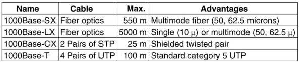
On the fibers a new encoding scheme 8B/10B is used. Each 8 bit byte is encoded as 10 bits. Not all of the 1024 possible codewords are used, no codeword may have more than 4 identical bits in a row or have more than 6 0's or 1's. This ensures that there are enough transitions in the stream to synchronize the receiver on the sender. Further many input bytes have two possible codewords assigned to them. The encoder than chooses the codeword that moves in the direction of balancing the number of 0's and 1's send so far. The keeps the DC component of the signal as small as possible to reduce the error rate.
All 4 pairs of Cat 5 cable are used to send 4 symbols, each representing 2 bits, in parallel. Thus there are 44=256 input possibilities, one byte is send in parallel. Each symbol is encoded in 5 voltage levels, this gives 54=625 output possibilities. They are chosen not in a fixed way but using an elaborate Trellis coding and Viterbi decoding which allow for error detection and correction by the receiver. Noise immunity is actually greater than for 100 Base-T. The rate of operation is 125 MHz, the same as with 100 Base-T, to give a data rate of 125MHz * 8 bits = 1 Gbps.
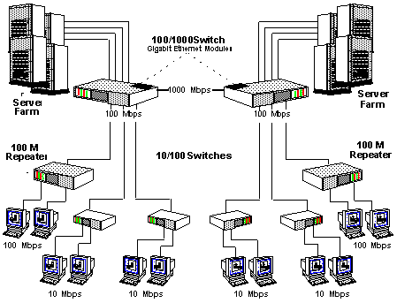 |
The whole range of 10, 100 and 1000 Mbps and 10/100 and 100/1000 switches provides for an easy upgrading strategy. This is possible because of the backward compatibility of all Ethernet standards. They offer unacknowledged datagram service with unicast and multicast, the same 48 bit addressing scheme and the same frame format, including the minimum and maximum frame sizes. |
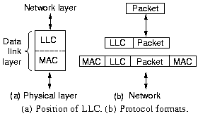 |
The 802 LAN's only provide for a best-effort datagram service. Sometimes, this is enough like for IP packets, which are simply inserted into the data part of 802 frames. For other situations a link level protocol, called LLC, is defined by IEEE. It provides 3 services: unreliable datagram, acked datagram and reliable connection oriented. The LLC header is based on the older HDLC protocol. |
Read this for important lessons, certainly if you want later to be a consultant on networks.
Physical Layer
| Name | Method | Medium | Rate | Coding |
|---|---|---|---|---|
| 802.11 | Infra red | 0.85 micron | 1 Mbps | 4 bits in 16 bits codewords |
| 802.11 | Infra red | 0.95 micron | 2 Mbps | 2 bits in 4 bits codewords |
| 802.11 | FHSS | 2.4 GHz ISM band | 1 Mbps | pseudorandom hopping using 79 1MHz bands |
| 802.11 | DSSS | 2.4 GHz ISM band | 1-2 Mbps | CDMA like with 11 chips |
| 802.11a | OFDM | 5 GHz ISM band | 54 Mbps | 236 bits in 288 bits codewords |
| 802.11b | HR DSSS | 2.4 GHz ISM band | up to 11 Mbps | 8 bits, 1.375 Mbaud |
| 802.11g | OFDM | 2.4 GHz ISM band | up to 54 Mbps |
The original 802.11 layers are seldom used. FHSS is suitable for building to building links because it is relative insensible to radio interference. This is important because ISM (Industry, Scientific, Medical) bands can be used without licenses. Garage door openers, cordless phones, radio-controlled toys, wireless mice, all use them. The 2.4 GHz band (from 2.4 to 2.4835 GHz) is much is use and is subject to interference from microwave ovens and radar installations. That is why Spread Spectrum methods, using many frequencies like CDMA, are required.
The 802.11b came before a and is used a lot. It also has versions with lower rates: 1, 2 and 5.5 Mbps. The data rate may be adapted dynamically during operations to achieve the optimum actual speed under current conditions of load, noise and multipath fading. The latter means that radio signals reflect on objects and may be received multiple times, delayed and attenuated. In practice the operating speed is nearly always 11 Mbps.
The higher speed of 802.11b is to be balanced with its lower range, a factor 7 less than 802.11a. The 802.11g was approved in November 2001, it is not yet clear whether its maximum speed can be reached in practice.
MAC sublayer protocol
This is different from Ethernet. There are the hidden and exposed station problems discussed earlier. Further most radios are half duplex, they cannot transmit and listen for noise burst at the same time at a single frequency. Both wireless networking with a base station, which is connected to standard Ethernet, and ad-hoc networking are supported.
For the latter DCF (Distributed Coordination Function) is used, which like Ethernet does not use any kind of central control. It uses CSMA/CA (Collision Avoidance) with both physical channel and virtual channel sensing. If a station wants to send, it first senses if someone is sending. If not, it transmits its entire frame which may well be destroyed at the receiver due to interference there. If the channel is busy, the sender waits until it goes idle and then starts transmitting. If a collision is detected (this might not be the case) a random time is waited, using the Ethernet binary exponential backoff algorithm, before trying again.
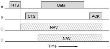
Virtual channel sensing is based on MACAW. RTS is used to ask permission to send, CTS to grand the permission and ACK to acknowledge the receiving of a correct data frame which terminates the exchange of frames. If the ACK timer expires before receiving an ACK, the sequence is repeated by the sender. The RTS and CTS frames contain an estimation of the time the rest of the sequence will take. Other stations which receive them, then know how long the virtual channel will be busy, and wait for it, indicated by NAV (Network Allocation Vector).
Wireless networks are noisy and unreliable compared to wired networks.
If the probability of any bit being in error is p, then the probability of an n-bit frame being received
correctly is (1-p)n. If p=10-4, the probability of receiving a full Ethernet frame of 12,144 bits
correctly is 29.7%, for p=10-5 about 11% of the frames will be damaged.
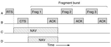
To deal with noisy channels, frames can be fragmented into smaller pieces, each with its own checksum.
The fragments are numbered and acknowledged using a stop-and-wait protocol. After the RTS and CTS exchange, fragments
can be send in a fragment burst. Fragmentation increases the throughput by restricting retransmissions
to the bad fragment rather than the entire frame. The NAV mechanism protects only the first fragment and its
acknowledgment, another mechanism protects the whole burst, see below.
A base station uses PCF (Point Coordination Function) to control all activities in its cell.
It polls the others stations to ask them if they have anything to send. The transmission order is completely
determined by the base station, no collisions ever occur.
A base station can adjust the fragment size to optimize the throughput.
The base stations broadcasts a beacon frame periodically (10 to 100 times per second) transmitting system
parameters and inviting new stations to sign up for polling service. A station can ask for a certain rate of polling and
it can be guaranteed to receive a certain fraction of the total bandwidth.
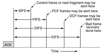
PCF and DCF can coexist in one cell, which at a first glance might seem impossible. Four time intervals are defined which restricts activities of stations after an ACK. In this way both PCF and DCF communications can proceed in an ordered way, not interfering with each other.
Frame structure
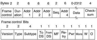
There are 4 different classes of frames: data, control and management. In addition there are some headers
used by the physical layer, mostly dealing with the modulation techniques used.
The data frame header contains 4 addresses, each in the standard 802 format. Two are used to identify
the sending and receiving stations. The other two are used for the source and destination of base stations for
intercell traffic. Remember that frames may leave or enter a cell via a base station.
The maximum data length is longer than the 1500 for Ethernet.
From the sequence field 12 bits are used to identify the frame and 4 bits the fragment.
The W bit in the frame control field indicates that the frame body has been encrypted using the
WEP (Wired Equivalent privacy), to provide some security.
Services
Nine services are provided in 802.11. The 5 distribution services relate to cell membership (portables can move) and interacting with stations outside the cell. The 4 station services relate to activity within a single cell.
The 5 distribution services are:
The 4 station services are:
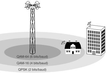
This protocol aims at multimegabit communication between a central antenna and antenna's on roofs buildings,
usable for voice, Internet, movies on demand, etc. Thus in competition with ADSL, cable TV and fiber to the house.
The distances involved can be several kilometers, thus the received power can vary widely.
This affects the signal-to-noise ratio, which is handled by using multiple modulation schemes
using 6, 4 or 2 bits per baud.
In contrast to 802.11 mobility of stations is not an issue. Further there can be many computers in a building,
meaning that more money can be spend on the radios, thus full-duplex communication can be used.
Also there are more users than in a typical 802.11 cell and they are expected to use more bandwidth
than an average 802.11 laptop user. More spectrum is needed than the ISM bands can provide, forcing the use of
the higher 10 tot 66 GHz range.
These millimeter waves have different physical properties than the longer waves in the ISM bands. They are strongly
absorbed by water, especially rain, but also by snow, hail and with bad luck heavy fog. Error handling is thus
more important than in 802.11. Millimeter waves can be focussed into directional beams, making the multipath problem less.
While 802.11 provides some support for real-time traffic (using PCF mode), it was not designed for telephony and heavy-duty
multimedia usage. In contrast, 802.16 is expected to support these applications completely.
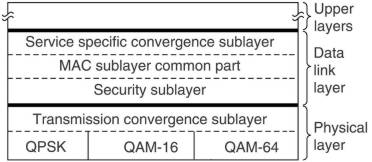
The physical layer has two sublayer. The top one hides the different transmission methods from the data link layer.
Work is under way to add more protocols to the lower sublayer: 802.16a will support OFDM in the 2-11 GHz range, 802.18b
will operate in the 5 GHz ISM band.
The data link layer consists of 3 sublayers. The security sublayer deals with privacy and security, crucial for public outdoor
networks. All frame payloads are encrypted using DES with cipher block chaining or triple DES. More encryption
methods will be added in the future. For authentication RSA public-key cryptography is used.
The MAC sublayer handles the main protocols, such as channel management. The base station controls
the system, it can schedule the downstream channels very efficiently and plays a mayor role in handling the
upstream channels as well. An unusual feature is that it is completely connection oriented, in order to provide
quality-of-service guarantees for telephony and multimedia communication.
The top sublayer provides the interface to the network layer to integrate seamlessly with both datagram protocols (IP, IPP) and
ATM.
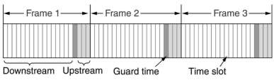
Two schemes are used to handle the allocate the bandwidth: FDD (Frequency Division Duplexing) and
TDD (Time Division Duplexing). In TDD the base station periodically sends out frames, each containing time slots.
The first ones are for downstream traffic, then comes a guard time used by stations to switch direction and fill the
next slots with upstream traffic.
The physical layer can pack multiple MAC frames back-to-back in a single physical transmissions.
This increases the effective data bandwidth by reducing the number of preambles and physical layer headers.
Hamming codes are used to do forward error correction, needed because of the expected high error rate.
The net effect is to make the physical channel look better then it really is.
In the same way as CD-ROMs appear to be very reliable, because more than half of the bits are used for
error correction in the physical layer.
A MAC frame is composed of several subframes, the first two are used to tell what is in which time slot
and which time slots are free. The allocation is closely connected to the 4 classes of
connection oriented services provided:
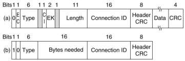
All MAC frames begin with a generic header of 48 bits. It is followed by an optional payload and an optional CRC. The latter is because of the error correction and the fact that no attempt is ever made to retransmit real-time frames. The EC bit tells whether the payload is encrypted, the EK bits which of the keys is used.
 |
LAN's can be connected by bridges, which operate at the data link layer. There can be many reasons to use them. 1) many departments could have started to install their own LAN's and only later came the need to connect them. 2) an organization might be geographically spread over several buildings, a single LAN might then be more expensive than connecting several LAN's. 3) it may be necessary to split what is logically a single LAN into separate LAN's to accommodate the load (switches could be use for this purpose also). 4) for reliability reasons it might be needed to use separate LAN's so that a single failure somewhere does not bring down the whole system. 5) for security reasons it might be needed to isolate a part, containing sensitive information, so that it can not be reached from outside. |
 |
A transparent bridge only requires connecting it to the LAN's. No software changes or downloading routing tables or parameters to it are needed. Also no changes are needed to the LAN's. It operates in promiscuous mode, accepting every valid frame arriving at its inputs. Then it must decide whether to discard it or forward it on one or more LAN's. This decision is make by looking up the destination address of the frame in a big (hash) table inside the bridge. |
Initially the hash tables are empty. The destination LAN of an incoming packet is not known, thus flooding is used: the packet is output to all LAN's, except the one it came from. But it knows then that the station with the source address of the packet is reachable from its input LAN. Thus it sets its table accordingly, this is called backward learning.
Hash table entries are marked with the last time that the entry is made or confirmed. Periodically all entries, older than a few minutes are purged. Thus if a computer is unplugged from a LAN and then installed on another one, after a few minutes it will be back in normal operation, without any manual intervention. It also means that if a station is quiet for a few minutes, any traffic to it will have to be flooded, until it sends itself a frame.
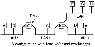
To increase reliability, some sites use two or more bridges in parallel between two LAN's. This creates loops in the topology, giving all kinds of problems: double arriving packets or long circulating packets.
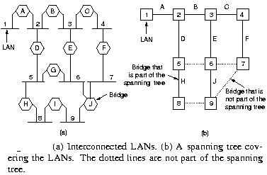 |
Spanning tree bridges communicate with each other and
overlay the actual topology with a spanning tree that reaches every LAN. |
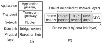
We have looked to various ways to get frames and packets from one cable segment to the other. They work in different layers, they can use different pieces of information to decide how to operate. In a typical scenario, the user generates some data to be sent to a remote machine. The data is passed to the transport layer, which adds a header, for example a TCP header, and passes the resulting unit down to the network layer. This layer adds its own header to form a network layer packet. This then goes to the data link layer, which adds its own header and checksum. The resulting frame is passed to the physical layer for transmission.
A repeater connects two cable segments, a signal appearing on one of them is amplified and reshaped, and them put out on the other segment. It does dot understand frames, packets or headers, only Volts. Classic Ethernet, for example, allowed 4 repeaters, in order to extend the maximum cable length from 500 to 2500 meters.
A hub has a number of input lines that it joines electrically. Frames arriving on any of them are sent out on all the others. If two frames arrive at the same time, a collision will occur, just as on a coaxial cable. The entire hub forms a single collision domain. Usually hubs do not amplify incoming signals. Like repeaters hubs do not examine the 802 addresses or use them in any way.
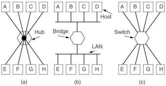
A bridge connects two ore more LAN's and operates at the data link layer. When a frame arrives, the destination address, for example the 48-bit Ethernet address, is extracted from the frame header and this is used to decide on which line to send the frame out. Each line is its own collision domain.
A switch also operates on the data link layer and uses the destination address for routing decisions. The main difference is that a switch is most often used to connect individual computers. Switches never lose frames due to collisions. However if frames come in faster than they can be retransmitted, a switch may run out of buffer space and then has to discard frames.
Nowadays, cut-through switches start forwarding frames as soon as the destination header field has arrived, but before the rest of the frame has arrived. This is handled completely in hardware, traditionally a switch contained an actual CPU that did the store-and-forward switching. All modern bridges and switches contain special integrated circuits for switching, the difference is more a marketing issue than a technical one.
A router operates at the network layer. It gets the packet out of a frame and uses the information in the packet header, for example the IP addresses, to decide where to send the packet to. This routing software (or hardware) does not even know whether the packet cam in over a LAN or via a point-to-point line.A transport gateway works on the transport layer. It receives for example a TCP packet (header and data) and uses the header information to decide what to do with the packet. This could be sending it out on another TCP/IP connection, or converting it to an ATM protocol stream of cells (the small packets of ATM).
Finally a application gateway understands the format and content of the data and translate massages from one format to another. An e-mail gateway could translate Internet messages into SMS messages for mobile phones
With the advent of 10Base-T and hubs in central wiring closets, it became possible to configure LAN's logically rather than physically. By putting a twisted pair cable in a closet into another hub, it is put on another LAN. So users which belong to a certain department can be put on 1 LAN independent of the physical location of their office. There are many reasons why that would be desirable: security, load, allocation of costs, etc. But a physical action of a system administrator, which costs time and is error prone. And you cannot if the offices are too far apart and the twisted pairs end in different closets.
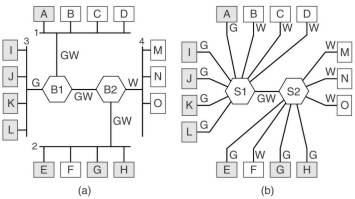
Virtual LAN (VLAN) is a concept to achieve the same effect by software means. Using special switches (or sometimes bridges) physical LAN's are organized into VLANs. In the figure one sees the gray and the white VLAN. A configuration table in each switch or bridge indicates which ports belong to which VLAN. It is possible that a port belongs to more than a VLAN (the GW lines in the figure), a complete separation is then not possible. A way to achieve that is to use the MAC address (e.g. the 48-bit Ethernet address) to indicate the VLAN. Another way is to use network layer protocol (e.g. IP or AppleTalk) or addresses (e.g. IP addresses). This however violates the independence of the layers.
A way out is to have a VLAN identifier in the data link frame header. For Ethernet the IEEE 802.1Q protocol provides a 4 byte addition to the standard header. At least the bridges and switches need to be able to handle this extension, they must be VLAN aware. If one of these connect to a traditional Ethernet interface of a computer, it must add or remove the extra bytes, using one of the 3 methods described above. It is expected that newer Ethernet interface cards for computers are also VLAN aware.
Note that the VLAN identifier introduces something similar to a connection. It is used as an index into a table inside the switch to look up were the frame is supposed to be sent. That is precisely what happens in connection-oriented networks. In connectionless networks, it is the destination address that is used for routing. This kind of mixing of connection-oriented and connectionless is slowly appearing at other places in the protocol stack. Its purpose is to add quality-of-services guarantees, more easily possible in connection-oriented networks, to connectionless networks, while preserving their perceived advantages.
Telecommunication operators now also provide VLAN services. With this a company can connect LAN's in different
buildings and organize them into VLANs. Computers connected to a single VLAN might thus be in different towns.
Gewijzigd op 11 februari 2003 door Theo Schouten.