A3 H5 The Network Layer
The network layer concerns with getting packets from the source
all the way to the destination which may require many hops through
intermediate routers. This contrasts with the data link layer, which
just moves frames from one end of a wire to another. To achieve its
goals the network layer must know about the topology of the
communication subnet ( the set of all routers) and choose appropriate
paths through it. It must take care to choose routers to avoid
overloading some of the lines and routers while leaving others idle.
When source and destination are in different networks, it has to deal
with the differences.
5.1 Network layer design issues
5.1.1 Store and forward packet switching
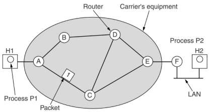
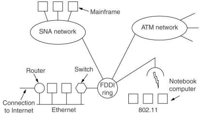
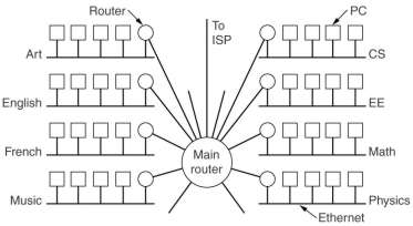
Inside the shaded oval is the carrier's equipment. Host H1 is directly connected to one of the carrier's
routers by a leased line. Host H1 is on a LAN with a router F, which also has a line to one of the carrier's routers.
Router F runs the same kind of algorithms as the carrier's routers, in that sense it can be regarded as part
of the subnet (see chapter 1).
A host with a packet to send transmits it to the nearest router, either on its own LAN or via a point-to-point
link to the carrier. The packet is stored there until it has fully arrived and the checksum can be verified.
Then it is forwarded to the next router along the path until it reaches the destination host.
5.1.2 Services provided to the transport layer
The network layer services to the transport layer have been designed with the following
goals:
- The services should be independent of the router technology
- The transport layer should be shielded from the number, type and
topology of the subnets present.
- The network addresses made available to the transport layer
should use a uniform numbering plan, even across LAN's and WANs.
A discussion point is whether the service should be
connection-oriented or connectionless. The Internet community argues
that a subnet is inherently unreliable, the hosts should do error
control and flow control. The service should thus be connectionless,
but as reliable as possible,
and the complexity is placed on the hosts. The telephone companies
argue that the subnet should provide a reliable, connection-oriented
service, placing the complexity in their subnets.
In the context of the internal operation of a subnet, a connection
is usually called a Virtual Circuit and the independent
packets of a connectionless organization are called datagrams.
5.1.3 Implementation of connectionless service
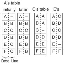
For datagrams each router needs a table telling which outgoing
line to use for each possible destination router.
This routing table is often updated according to the situation in the subnet.
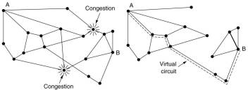
In the figure, A initially sends packets for E and F over its line to C.
Then A changes its mind and decides to route packets for E and F over B.
There might be many reasons for this,
A might have learned that there was a traffic jam at C or that the line between C and E is out of service for a while.
It might then be that the first three packets go over C and the fourth one over B. That 4th packet
one might arrive earlier at F than the third and even the second and first packets.
A routing algorithm is used to manage the tables on which the routing decisions are based.
A datagram must have the full destination (and often the source) address in its header,
which can be quite long for large networks. From that it must be possible to determine
the final destination router
5.1.4 Implementation of connection-oriented service
For VC's, a route from the source to destination is chosen as part
of the connection setup. For this the setup procedure uses the same kind of tables as a datagram subnet.
Once a connection is setup, it gets an unique VC number. Each router along the chosen path puts an entry in a table,
linking the VC number to an outgoing line. Every further packet of an connection contains in its header its VC number,
so every router knows were to send it.
5.1.5 Comparison of Virtual Circuit and Datagram subnets
| Issue |
Datagram subnet |
VC subnet |
| Circuit setup |
Not needed |
Required |
| Addressing |
Each packet contains the full source and destination address |
Each packet contains a short VC number |
| State information |
Subnet does not hold state information |
Each VC requires subnet table space |
| Routing |
Each packet is routed independently |
Route chosen during setup; all packets of a VC follow this route |
| Effect of router failures |
None except for packets lost during the crash |
All VC's that passed through the failed router are terminated |
| Quality of service |
Difficult to guarantee |
Easy if enough resources can be allocated during the setup procedure |
| Congestion control |
Difficult |
Easy if enough buffers can be allocated in advance for each VC |
Tradeoffs:
- router memory space versus bandwidth
- setup time versus address parsing time
5.2 Routing algorithms
The main function of the network layer is routing packets from the
source machine to the destination machine, often requiring multiple
hops. For broadcast networks routing is an issue if source and
destination are not on the same network. The routing algorithm
is that part of the network layer software responsible for deciding
which output line an incoming packet should be transmitted on. With
VC's networks one speaks of session routing, because a route
remains in force for an entire user session (e.g. a login session or
a file transfer). The following properties are desirable in a routing
algorithm:
- correctness and simplicity.
- robustness, against software and hardware failures, traffic
changes and topology changes for very long periods.
- stability, some algorithms never converge to an equilibrium.
- fairness and optimality, which are conflicting goals.
 |
If A-A', B-B' and C-C' have enough traffic to saturate the horizontal
links, the total flow is maximized if the X-X' traffic is shut off completely.
Several measures can be optimized, like maximizing total
network throughput or minimizing mean packet delay.
Note that these goals are in conflict, operating any queuing
system near maximal capacity implies long queuing delays. As a
compromise, many networks attempt to minimize the number of hops a
packet must make, this tends to improve the delay and reduces the
amount of bandwidth consumed, which tends to improve the throughput as well.
|
Nonadaptive algorithms calculate the routes from any source
to any destination in advance, off-line, and download this
information to all routers when the network is booted. This is also
called static routing.
Adaptive algorithms change their routing decisions to
reflect changes in topology and usually traffic as well. They differ
in where they get their information from (e.g. locally, from adjacent
routers, from all routers), when they change the routes (e.g. every n
seconds, when the load or topology changes) and what metrics used for
optimization (e.g. distance, number of hops, estimated transit time,
cost for carriers).
5.2.1 The optimality principle
 |
One can make a statement about optimal routes without regard to
network topology or traffic. The optimality principle states that if router J is on the
optimal path from router I to router K, then the optimal path from
J to K also falls along the same route.
As a consequence, the set of optimal routes from all sources to
a given destination form a tree routed at the destination. This is
shown here using as distance metric the number of hops. Note that
other trees with the same path length exist.
|
Such a tree is called a sink tree, as it does not
contain loops, each packet will be delivered in a bounded number of hops.
5.2.2 Shortest path routing
Here the subnet is described as an undirected graph, with each
node representing a router and each arc representing a communication
link. Each arc is labeled with a length and Dijkstra's (or another)
algorithm is used to compute the path with the shortest length
between any two nodes.
Several metrics of length are possible. When using the number of
hops as a measure, each arc as a length of 1, as was used in the figure
above. If physical distance was taken as a measure, M would go over L.
In general the labels on the arcs can be computed as a function of
distance, bandwidth, average traffic, communication costs, mean queue
length, measured delay, etc.
5.2.3 Flooding
Another static algorithm is flooding, in which every
incoming packet is sent out on every outgoing line except the one it
arrived on. It generates a vast number of duplicate packets, in fact,
an infinite number unless some measures are taken to damp the
process. One possibility is to use a hop counter in the header of
each packet, which is decremented at each hop, and the packet is
discarded when the counter reaches 0. In selective flooding
the packets are only sent out on those lines that are going
approximately in the right direction.
Flooding might be usable in military applications, where large
numbers of routers may be blown to pieces at any instant, as it is
very robust.
In wireless networks all messages transmitted by a station can be received by all other stations
in its radio range. This is, in fact, flooding, and some algorithm uses this property
5.2.4 Distance vector routing
This algorithm, also called Bellman-Ford or Ford-Fulkerson, is a
dynamic routing algorithm. Each router maintains a table (a vector)
giving the best known distance to each destination and which line to
use to get there. These tables are updated by exchanging information
with the neighbors. It was the original ARPANET routing algorithm,
also used in Internet under the name RIP and in early versions of
DECnet and Novell's IPX. Appletalk and Cisco routers use improved versions.
 |
A routing table in each router contains for each router in the subnet the preferred
outgoing line for that router and an estimate for the time or
distance to that destination. The metric might be number of hops,
queue length, time delay, etc. Time delay can be measured by
periodically sending special ECHO packets.
Once every T msec each router sends to its neighbors a list of
estimated time delays to each destination.
Router J then calculates that it can go to e.g. G via A in
(8+18)=26, via I in 41, via H in 18 and via K in 37 msec. The
lowest (via H in 18 msec) is then chosen and put in the table.
|
In practice it has a serious drawback, it react slowly to bad
news, know as the count-to-infinity problem. Many ad-hoc solutions
to this problem have been proposed. The widely used split-horizon
hack (which reports the time to X on the line that packets for X
are sent on as infinity) has geometries in which it offers no improvement.
The core of the problem is that when X tells Y that it has a path somewhere,
Y has no way of knowing whether it itself is on the path.
5.3.5 Link state routing
This replaced distance vector routing used in ARPANET in 1979.
Each router must:
- Discover its neighbors and learn their network addresses, by
sending HELLO packets on each point-to-point line and receiving the
reply messages. A LAN is often modeled here as an artificial node.
- Measuring the cost or delay (using ECHO packets) to each of its
neighbors. The load can be taken into account or not by starting the
round-trip timer when the packet is queued or when it is send.
- Construct a link state packet telling all it has just learned. This is done at
regular time intervals, or when a significant event occurs.
- Send this packet to all other routers using flooding.
- Compute the shortest path to every other router using e.g.
Dijkstra's algorithm or modifications thereof to avoid to much
problems when some information is wrong due to hardware of software
failures.
The trickiest part is distributing the link state packages reliably,
to assure that each router has basically the same view of the subnet.
The link state packet contains a 32 bit sequence number
(sufficient for 137 years, if it is updated every second). An age
field is decremented every second and at every send and the packet is
discarded if the age reaches 0. If a router crashes and starts from sequence
number 0, after a while all its higher sequence number packets have died and the new packets
are regarded as valid.
To make it more robust a received
link state packet is not send out immediately but it is stored in a
holding area. Newly arriving packets are compared with the ones in
the holding area to discard e.g. ones with lower sequence numbers.
Also all link state packets are acknowledged.
5.2.6 Hierarchical routing
 |
As networks grow, the router table grow proportionally. CPU time to
scan and process the table also grows and more bandwidth is needed
to send link status packets. With hierarchical routing, the
routers are divided into regions. A router knows the details of
its region but not of the other regions.
The routing table gets smaller, but certain path length get
longer. All traffic to region 5 is routed via region 3, because
that is the best for all routers except 5C.
A hierarchy can have more than 1 level. It can be shown that
the optimal number of levels for N routers is ln(N), requiring a
total of e*ln(N) entries per router. The increase in effective mean
path length is usually acceptable.
|
5.2.7 Broadcast routing
In some applications, hosts needs to send messages to many or all other hosts,
like a host sending a live radio or tv program. Sending a packet to all destinations simultaneously
is called broadcasting.
One possibility is to send a distinct packet to each destination. This wastes bandwidth and requires
that all destinations are known, but often it is the only possibility.
Also flooding is a possibility.
In multi-destination routing each packet contains a list of destinations, or a bit map indicating
the desired locations. A router receiving such a packet, checks all the destinations to determine the
output lines that will be needed. For each of them a copy of the packet is generated with the destinations reduced
to the destinations reachable.
If the sink tree of the router originating the broadcast is known and other routers know
which of their lines belong to it,
then a router receiving a packet over a sink tree line, sends it out over its other sink tree lines.
In stead of the sink tree, any other spanning tree can be used. This is a subset of the subnet
that contains all the routers but contains no loops.
This method makes excellent use of the bandwidth, generating the absolute minimum number of packets
needed for the job. A problem is that each router must have local knowledge of a global spanning tree.
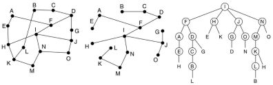
With the reverse path forwarding algorithm when a router receives a broadcast packet, it checks whether it arrives
on the line the router uses for sending packets to the source of the broadcast.
If so, it is likely that the broadcast also followed that route, and the packet is send out over all other lines of the router.
Otherwise the packet is discarded.
The images show from left to right a subnet, a sink tree starting at I and the tree build by reverse path forwarding.
There after 5 hops and 24 packets the broadcast terminates, compared to 4 hops and 14 packets had the sink tree
be followed exactly. The reverse path forwarding is both reasonable efficient and easy to implement
5.2.8 Not for this course
5.2.9 Routing for mobile hosts
Hosts that never move are said to be stationary. The others are mobile hosts.
They can migratory, these move from one fixed site to another from time to time but use the network only when they
are physically connected to it. Roaming hosts actually compute on the run and ant to maintain their connections as they
move around.
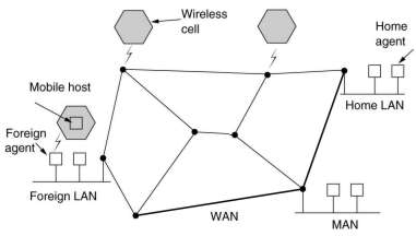
All hosts are assumed to have a permanent home location that never changes. The world is divided up into small
areas, typically a LAN or a wireless cell. Each area has one or more foreign agents, which are processes
that keep track of all mobile hosts visiting the area. Each area also has a home agent which keeps track of hosts whose home is
in the area, but which are currently visiting another area. When a new hosts enters an area, it must register itself with the
foreign agent:
- Periodically each foreign agent broadcasts a packet announcing its existence and address. A mobile host can also broadcast
a request for it.
- The mobile host registers with its home address, current data link layer address and security information.
- The foreign agent contacts the mobile host's home agent with this information.
- This is checked there.
- If ok, the foreign agent makes a registration entry in its tables and informs the mobile host.
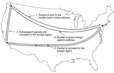
When a packet is send to a mobile host, it is routed to the host's home LAN, where it is intercepted by the home agent.
That finds the new (temporary) location and address of the foreign agent handling the mobile host. Then it sends
the packet, encapsulated in another packet, to the foreign agent, which sends it to the mobile host. The home agent
also sends the foreign agent address to the original sender. Further packets to be send are then send directly to
the foreign agent, also encapsulated.
Various variations have been proposed which differ in various aspects.
5.2.9 - 5.2.11 Not for this course
5.3 Congestion control algorithms
When too many packets are present in a subnet, performance degrades, a
situation called congestion. Buffers get full, so packets
are discarded leading to more retransmissions and less packets
delivered to their destinations. Adding memory might help, but
then the queues get longer leading to more time-outs and
retransmissions. Congestion thus tends to feed upon itself and
become worse, leading to collapse of the system.
Congestion control has to make sure that the subnet is able to
carry the offered load. It is a global issue, involving the
behavior of all hosts and routers.
In contrast, flow control relates to the point-to-point traffic
between a sender and a receiver, making sure that the sender is
not overloading the receiver.
The reason congestion and flow control are often confused is
that some congestion control algorithm operate by sending messages
back to various sources, telling them to "slow down".
Thus a host can get a "slow down" message either because
the receiver cannot handle the load or because the network cannot handle it.
5.3.1 General principles of congestion control
| Open loop |
prevention by good design |
source |
| destination |
| Closed loop |
monitor system
congestion info to action points
adjust system operation |
explicit feedback |
| implicit feedback |
Two solutions to the presence of congestion: increase the
resources or decrease the load. The subnet might start using
dial-up telephone lines to temporarily increase the bandwidth
between points. Spare routers, reserved for backups to make the
system fault tolerant, could be put on-line. Decreasing the load
might include denying service to some users or degrading service
to all or some users.
5.3.2 Congestion prevention policies

There are many policies on different layers that affect congestion
An important issue here is the setting for timers, if they are set
too low extra retransmissions occurs. Adaptive setting of timers is needed.
Sliding window protocols using selective repeat give less
retransmissions than using "go back n". Using piggybacking
for acks reduces the number of packets, but adds an extra timer
involving a chance of extra retransmissions. Using a smaller window
size reduces the data rate and thus help fight congestion.
When virtual circuits are used it is easy to deny new connections
in case a congestion is near.
A routing algorithm can help avoid congestion by spreading traffic
over all possible routes, in stead of the best one.
5.3.3 Congestion control for virtual circuit subnets
With admission control once congestion has been signaled, no more virtual circuits are set up
until the problem has gone away. This is a crude approach, but it is simple and easy to implement.
Another way is to route new connections around the problem area. The subnet is "redrawn" leaving
congested routers and all their lines out and then determine the best route for a new connection in that subnet.
A step further is to try to avoid routers that are directly connected to the congested routers.
Another strategy is to negotiate an agreement between the host and subnet when the connection is set up.
This would specify the volume and shape of the traffic, quality of service and other parameters. To keep its part
of the agreement, the subnet will typically reserve resource along the path the VC is set up. This can include
table and buffer space in the routers and bandwidth on the lines. In this way congestion can be avoided.
This kind of reservation can be done always, but this tends to waste resources. If 6 VC's that might use 1 Mbps pass through
a 6 Mbps line, this line has to be considered full, even though it may rarely happen that all 6 VC are transmitting at full
speed at the same time. The reservation can also only be done when there is a congestion on the subnet.
In general the price of congestion control is unused and wasted bandwidth.
5.3.4 Congestion control for datagram subnets
Each router can easily monitor the utilization of its output lines and other resources.
In the old DECNET a warning bit was set in the header of a packet send out over a too busy line or when
the router is low on buffer space.
At the destination, the transport entity copied this bit into the next acknowledgment sent to the source,
which reacts by reducing the transmission rate. This continues when more warning bits come in.
When no more warning bits arrive, the transmission rate is increased slowly.
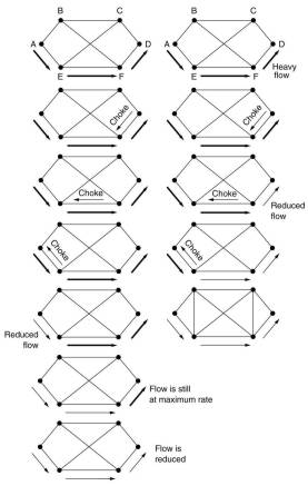
A router can also directly send a choke packet back to the source host of a packet send out over a too busy line.
That packet is tagged so that it will not generate more choke packets on its way.
When the source host receives the choke packet, it reduces its rate to the specified destination by a certain fraction.
If it receives a choke packet in reaction to its new rate, it reduces again by that fraction.
For high speeds or long distances, the reaction is too slow.
With hop-by-hop choke packets each intermediate router also reacts on a choke packet by reducing its sending rate.
For that it needs sufficient buffers to store the packets which still come in at a too high rate.
5.3.5 Load Shedding
A fancy way of saying that when routers are being inundated by packets that they cannot handle, they just throw them away.
Depending on the application the packet is used for, this can be done so that triggered retransmissions are reduced.
For example, for file transfers it is best to throw away newer packets, for multimedia older packets are best.
Applications can indicate the priority and action in case of congestion of their packets in the headers of them,
for example in IP.
In random early detection routers drop packets before the situation has become hopeless,
for example when their buffers are filled above a certain fraction. As it is difficult to tell
which source contributes most to the trouble, a random selection of the packets to drop is used.
A choke packet could be sent to the source of a dropped packet, with a disadvantage that it puts even more load
on an already congested network. Fortunately, in most transport protocols designed for rather reliable wired networks, like TCP,
it was realized that lost packets are mostly due to buffer overruns somewhere rather than transmission errors.
These protocols respond to a lost packet by temporarily reducing the sending rate, so a choke packet is not needed there.
In wireless networks most losses are due to noise on the air link, here choke packets are needed.
5.3.6 Jitter control
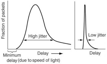
For applications such as audio and video streaming, it does not matter much if the packets take 20 or 30 msec to be delivered,
as long as the transit time is constant. The standard deviation in transit times is called jitter
This can be bounded by computing the expected transit time for each hop. When a packet arrives at a router, it is checked
how much the packet is behind or ahead its schedule. This is stored in the header and updated at each hop.
The router sends then always the packet which is furthest behind.
In some applications, like video on demand, jitter can be compensated for by buffering at the receiver.
For others, like Internet telephony or videoconferencing, the delay inherent in buffering is not acceptable.
5.4 Quality of Service
5.4.1 Requirements
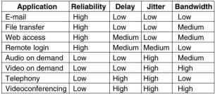
QoS is determined by four primary parameters: reliability, delay, jitter and bandwidth.
The table shows how stringent these requirements are for various applications.
ATM networks classify flows into 4 broad categories with respect to their QoS demands, a division which is
also useful for other networks:
- Constant bit rate (e.g. telephony), attempts to simulate a wire, providing uniform bandwidth and delay.
- Variable bit rate (e.g. compressed videoconferencing),images must arrive in time independent on how much
they could be compressed.
- Non-real-time variable bit rate (e.g. watching a movie over internet), a lot of buffering at the receiver is allowed.
- Available bit rate (e.g. file transfer), applications that are not sensitive to jitter or delay.
5.4.1 Techniques for achieving good QoS
Overprovisioning means to provide so much router capacity, buffer space and bandwidth that all the
packets just fly through easily. The problem with this is that it is expensive.
But as time goes on and design and technology improves, it sometimes even becomes practical.
The telephone system is an example, it is rare to pick up a telephone and not get a dial tone instantly.
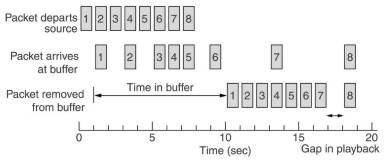
Buffering. Flows can be buffered on the receiving size before being delivered to a monitor or speaker.
It does not affect the reliability or bandwidth, it increases the delay, but it smoothes out the jitter.
For audio and video on demand, jitter is a main problem, so it helps here.
Commercial web sites that contain streaming audio or video all use players that buffer for about 10 seconds
before starting to play. If the bandwidth is low, much more must be buffered, or the whole play must be first stored
on a local disk.
One of the main causes of congestion is that traffic is often bursty.
If hosts could be made to transmit in a more uniform rate,
congestion would be less common. Traffic shaping is about
regulating the average rate and burstiness of data transmission,
it is widely used in ATM.
 |
The leaky bucket algorithm to regulate the maximum
number of packets (or bytes) per time unit. When the bucket is
full, packets are discarded.
When the packets are all the same size (as in ATM), the algorithm can be used as described.
When variable-sized packets are used it is often better to allow for a fixed number of bytes per tick.
|
 |
The token bucket algorithm allows the output rate to speed up
to a certain maximum when a large burst arrives from the host computer. Tokens are used
to accumulate rights to send packets or bytes. Packets are less
likely to be discarded.
Sometimes a token bucket is followed by a leaky bucket.
|
5.5 Internetworking
 |
If two or more networks are connected we speak of an internet.
Various boxes working on different protocol layers can be used
for internetworking, see chapter 4.
|
5.5.1 How networks differ
| Item |
Some possibilities |
| Service offered |
Connection-oriented versus connectionless |
| Protocols |
IP, IPX, CLNP, AppleTalk, DECnet, etc./ |
| Addressing |
Flat (802) versus hierarchical (IP) |
| Multicasting |
Present or absent (also broadcasting) |
| Packet size |
Every network has its own maximum |
| Quality of service |
May be present or absent; many different kinds |
| Error handling |
Reliable, ordered or unordered delivery |
| Flow control |
Sliding window, rate control, other or none |
| Congestion control |
Leaky bucket, choke packets, etc. |
| Security |
Privacy rules, encryption, etc. |
| Parameters |
Different time-outs, flow specifications, etc. |
| Accounting |
By connect time, by packet, by byte, or not at all |
5.5.2 How networks can be connected
See chapter 4, and the review of Tanenbaum here.
5.5.3 Concatenating virtual circuits
A sequence of virtual circuits is set up from the source trough one
or more gateways to the destination. Each gateway maintains tables
telling which virtual circuits pass through it, where they are to
be routed, and what the new virtual circuit number is. Once data
packets begin flowing, each gateway relays incoming packets,
converting between packet formats and VC numbers as needed. As all
packets must transverse the same sequence of gateways, they arrive in order.
This scheme works best when all the networks have roughly the
same properties. It can not be used if one of the subnets does not
offer VC's but only datagrams.
5.5.4 Connectionless internetworking
As a routing decision is made for each packet, possible depending on
the traffic, packets might arrive out of order. But a higher
bandwidth might be achieved than when concatenating VC's.
Addressing is a problem if e.g. an IP packet with 32 bit
addresses has to be send to an OSI host with decimal addresses
similar to telephone numbers. One would need an IP number for the
OSI host and an OSI number for the IP host, to make the conversion
in the multiprotocol routers. This is impossible on a large scale
with the current IPv4 protocol.
The properties of the datagram approach to internetworking are
the same as those of datagram subnets: more potential for
congestion but also more potential for adapting to it, robustness
in the face of router failures and longer packet headers.
5.5.5 Tunneling
 |
Tunneling can be used when the source and destination hosts are on the same
type of network, but there is a different network in between. The
packets to be send are just put in the payload of the connecting network.
An analogy is putting your car on a train which then uses the
tunnel under the English Channel.
|
5.5.6 Internetwork routing
This is similar to routing within a single subnet with some additional
complications. Routers might prefer routes with no protocol
conversions over ones that use tunneling over ones that need
protocol conversions, even if those routes are longer. Subnets
might be run by different carriers and have different charging
algorithm, so routing might be based on cost. When international
boundaries are crossed the various laws come into play, such as
Sweden's strict lays about exporting personal information about
Swedish citizens. Another example is the Canadian law saying that
Canadian traffic with source and destination within Canada may not leave the country.
5.5.7 Fragmentation
Each network imposes some maximum size on its packets, due to
various causes. Among them: hardware (e.g. the width of a TDM
transmission slot), operating system (e.g. buffers of 512 bytes),
protocols (e.g. number of bits in the length field), compliance with
some standard, desire to reduce error induced retransmissions, desire
to prevent packet from occupying the channel too long. Besides
starting with packets which are small enough for each intermediate
network and gateway, a solution is to allow gateways to break packets
up into fragments.

With transparent fragmentation, when an oversized packet arrives
at a gateway, it is fragmented and all the packets are send to the
same exit gateway of the subnet, where the fragments are
recombined. Fragments must be numbered and the last one must be
somehow indicated. Passage through the small-packet subnet has
been make transparent:, subsequent subnets are not aware that this
has occurred. ATM networks, for example, have special hardware to
provide transparent fragmentation (there called segmentation) of
packets into ATM cells and then reassembly of cells into packets.
With nontransparent fragmentation, once a packet is
fragmented it is only reassembled when the destination is reached.
This requires that every host is able to do reassembly.
5.6 The network layer in the Internet
Tanenbaum states the principles that drove the design of the network layer in Internet
and made it the success that it is today. Read it carefully.
 |
At the network layer, the Internet can be viewed as a collection of
subnetworks or Autonomous Systems (AS). There is no real
structure, but several mayor backbones exist, constructed from
high bandwidth lines and fast routers. Attached to them are
regional networks and to these the LAN's at many universities,
companies and Internet Service Providers.
The glue that holds Internet together is the network layer
protocol Internet Protocol (IP). It provides a best-effort
way to transport datagrams from source to destination, whether or
not these machines are on the same network, or whether or not
there are other networks in between them.
|
5.5.1 The IP protocol
The header of an IP datagram has a 20-byte fixed part and a variable
length optional part. It is transmitted in big endian order: from
left to right, the high-order bit of the Version field going
first. The SUN Sparc is big endian, the Pentium is little endian,
requiring conversion on both transmission and reception.
This is usually done in hardware.
The Version field holds the version of the protocol the
datagram belongs to. The IHL field tells how long the header is,
in 32 bit words. The minimum is 5, the maximum is 15, providing
for a 40 byte option field.
The Type of Service field contains a 3
bit Precedence field, used for the priority from 0 (normal) to 7
(network control packet), and 3 flags Delay, Throughput and
Reliability, to specify what is most important for the packet. In
practice, current routers mostly ignore the TOS field.
The Total Length includes everything in the datagram, with a maximum length
of 65,535 bytes. At present this is tolerable, but with future
gigabit networks larger datagrams will be needed.
All fragments of a datagram have the same Identification field,
the Fragment Offset tells where in the current datagram this
fragment belongs, in units of 8 bytes. All fragments, except the
last one which is indicated with a MF of 0, must thus be a
multiple of 8 bytes. A DF flag of 1 indicates that the datagram
should not be fragmented because the destination is not able to
put the pieces together. All machines are required to accept
datagrams or fragments of 536 bytes or less.
The Time to Live field is a counter used to limit packet
lifetimes, it must be decremented at each hop. The packet is
discarded when TOL hits 0. The Protocol field tells the receiving
host which transport process (TCP, UDP or other) the packet should be
given to. The Header checksum verifies the header only, useful for
detecting errors by bad memory bytes or corrupted software inside a
router. It must be recomputed at each hop, because the TOL changes.
| Option |
Description |
| Security |
Specifies how secret the datagram is (ignored in practice) |
| Strict source routing |
Gives the complete path to be followed (used by system managers
for timing
or sending emergency packets when the routing
tables are corrupted) |
| Loose source routing |
Gives a list of routers not to be missed (used to dictate
passing through or avoiding
certain countries or regions) |
| Record route |
Makes each router append its IP address (allow to track down
bugs in the routing algorithms) |
| Timestamp |
Makes each router append its address and timestamp (also for
debugging) |
5.6.2 IP addresses
All IP addresses are 32 bits long, there exists 5 formats for them.
The multicast format allows to direct a datagram to multiple
hosts. The class A, B resp. C formats allow for 126, 16382 resp. 2
million networks with 16 million, 64K resp. 254 hosts.
Network numbers are assigned by the NIC (Network
Information Center) to avoid conflicts. They are usually written
down in dotted decimal notation, each of the 4 bytes is
written in decimal from 0 to 255.
The IP address 0.0.0.0 is used by hosts when they are being booted but
is not used afterwards. IP addresses with 0 as network number
refer to the current network. The address 255.255.255.255 allows
broadcasting on the local network, typically a LAN. The addresses
with a proper network number and all 1's in the host field, allow
a broadcast on the distant network. All addresses 127.x.y.z are
for loopback testing, packets sent to that address are not put on
the wire, but just put in the input queue of the same machine.
This allows for debugging network software.
Subnets
 |
All the hosts in a network must have the same network number.
As the number of computers in an organization, like a university growed and the length of the Ethernet cable
to connect them, the maximum length of the cable was reached.
Getting another network number was difficult as they were scarce and probably
the organization already had a class B address, sufficiently for 64K hosts.
The solution was to allow a network to be split into several parts for internal use,
but still act like a single network to the outside world.
|
The 2 level hierarchy (network, host) can be extended to a 3 level
(network, subnet, host) hierarchy. Note that here the use of
"subnet" conflicts with the meaning of the set of all
routers and communication lines in a network.
The network field stays the same, the outside world does not
see subnets. But internally the host field is split into the
subnet and host field, with reduced size. This allows a router on
a subnet to only know the hosts on its own subnet, not on the
other subnets. This reduces router table space.
CIDR: Classless InterDomain Routing
IP has worked extremely well, as demonstrated by the exponential
grow of Internet the last years. Unfortunately IP is running out of
addresses. A problem is that class C networks, with maximal 256
addresses, is so small that most organizations ask for a class B
network with 64K addresses, of which there are only 16K. In fact, a
class B network is too large for most organizations, half of these
networks appear to have fewer than 50 hosts. Another problem is the
space needed for the routing table, routers have to know about all
the hosts. The complexity of various algorithms for the management of
the tables is more than linear, creating a speed problem.
A solution is CIDR. A basic idea
is to allocate the remaining class C networks (more than 2 million)
in variable sized blocks, a site needing 8000 addresses then gets 32
contiguous class C networks. The world was divided up into 4 zones. A
site outside Europe, that gets a packet destinated for 194... or
195... can just send it to its standard European gateway. In effect
32 million addresses have now been compressed into one routing table
entry.
Each routing table entry is now also extended with a 32 bit mask.
A destination address is now ANDed with a mask before being compared
with the corresponding address in the routing table. It is possible
that 2 entries match, in which case the match with the most 1's is
chosen. Indexing tricks are used to speed up the search.
The same idea is applied to all addresses, so with CIDR the old
class A, B and C networks are no longer used for routing. This is why
CIDR is called classless routing.
NAT Network Address Translation
IP addresses are scarce. An ISP might have a /16 (formally class B) address, giving 64K host numbers. If it has
more customers than that, it might give each customer with a dial-up connection an
dynamically assigned IP number when it logs in. Normally not all customers are logged on at the same time.
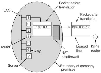
Another way out is using NAT. Within a company internal IP addresses of the form 10.x.y.z are used.
When communicating with the outside world, all internal IP numbers are changed to an external number.
The problem occurs when a packet comes back (e.g. from a WEB server). How does the NAT know which internal IP number
to use? Many internal computers might be communicating with the same WEB server.
The dirty solution is that most IP packets carry a TCP or UDP payload. Their headers contain a field, a 16 bit
source port, which indicates which process on the sending machine has send the TCP or UDP payload.
The receiving machine uses this port number, now placed in the destination port to send information back.
On sending the NAT replaces the source port with an index to a table, containing the real internal IP and source port.
On receiving it looks up that information and changes the incoming packet accordingly.
The method as important disadvantages. It violates the whole hierarchical architectural model. It makes the IP network
in fact connection-oriented as it maintains information on each connection passing through it.
A crash of the NAT box terminates every TCP connection. Further there are some protocols, like FTP
and the H.3232 Internet telephony protocol, which send IP numbers (and port numbers) in data, to be used by the other side.
These protocols fail unless certain precautions are taken or patches are installed in the NAT software.
NAT is useful as an intermediate solution until version 6 of IP, with a much larger IP bursty space, is in widely use.
5.6.3 Internet control protocols
In addition to IP, which is used for data transfer, the Internet
has several control protocols.
Internet Control Message Protocol (ICMP)
| Message type |
Description |
| Destination unreachable |
Packet could not be delivered |
| Time exceeded |
Time to live field reached 0 |
| Parameter problem |
Invalid header field |
| Source quench |
Telling sending host to slow down |
| Redirect |
Teach a router about geometry |
| Echo request |
Ask a machine if it is alive |
| Echo reply |
Yes, I am alive |
| Timestamp request |
Same as Echo request, but with timestamp |
| Timestamp reply |
Same as Echo reply, but with timestamp |
When something unexpected occurs in a router or host, this event
is reported by ICMP. It is also used by routers to test the internet or to obtain information
to be use in routing decisions.
The most important message types are given in this table.
Each ICMP message is encapsulated in an IP packet.
Address Resolution Protocol (ARP)
How do IP addresses get mapped onto data link layer addresses,
such as Ethernet or FDDI addresses? One solution is to have a
manually build configuration file somewhere in the system that
provides the mapping.
With ARP the host broadcast a frame asking who owns a certain IP
address, like E1 asking for 192.31.65.5. Host E2 alone will answer
with a broadcast frame telling its IP and ethernet number. All
machines seeing this, will put the (IP, Ethernet) pair in an ARP
cache for further use. As an optimization E1 will put its pair in
the asking broadcast, thus all machines cache that information.
What if E1 wants to send a message to E4? One possibility is to
configure the CS router to respond to ARP request for network
192.32.63.0, thus E1 and E2 make an entry (192.32.63.x,E3) in
their cache. This is called proxy ARP. Another possibility
is to have hosts on CS immediately see that the destination is on
a remote (sub)network and send all such traffic to a default
Ethernet address that handle all such traffic, such as E3.
To allow mappings to change (e.g. replacing a faulty Ethernet
interface card), entries in the ARP cache should time out after a
few minutes.
RARP, BOOTP and DHCP
These protocols solve the reverse question: given an Ethernet address what
is the IP address? This situation occurs e.g. when booting a diskless
workstation. But DHCP is now used in many networks for all user machines.
A RARP server, one on each network, sees the locally broadcast RARP request,
looks up the IP address in a configuration table and sends back the
corresponding IP address.
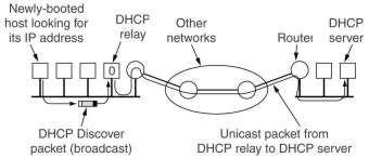
The BOOTP protocol uses UDP messages, which are
forwarded over routers. It also provides diskless workstations with
additional information, like the IP address of the server holding its
memory image, the IP address of the default router, and the subnet
mask to be used.
DHCP (Dynamic Host Configuration Protocol) eliminates the need for configuration tables mapping IP bursty to Ethernet bursty.
It can assign IP addresses dynamically.
5.6.4 An interior gateway routing protocol: OSPF.
 |
The Internet is made up of a large number of autonomous systems
(AS). Each AS is operated by a different organization and can use its
own routing algorithm (called an interior gateway protocol) inside.
The OSPF (Open Shortest Path First) algorithm became a
standard in 1990. It support 3 kinds of connections and networks:
point-to-point lines between exactly 2 routers, multi-access networks
with broadcasting (most LAN's) and without broadcasting (most packet-switched WANs).
Each AS might be divided up into numbered areas, a
generalization of subnets. Outside an area, its topology and
details are not visible. Within an area, each router has the same
link state database and runs the same shortest path algorithm.
Area 0 is the backbone, all other areas are connected to it, possible via tunnels.
|
OSPF distinguishes 4 classes of routers: internal routers, area border routers, backbone routers
and AS boundary routers. The classes may overlap, e.g. all the
border routers are backbone routers.
Type of service is handled
by having 3 graphs, labeled with costs when delay, throughput or
reliability are the metric.
| Message type |
Description |
| Hello |
Used to discover the neighbors
When booted on
point-to-point links,
multicasted on LAN's, send on WANs |
| Link state update |
Provides the sender's costs to its neighbors
Periodically
flooded to adjacent routers
contains sequence numbers |
| Link state ack |
Acks link state update |
| Database description |
Announces which update seq numbers
the sender has, used
when line is brought up. |
| Link state request |
Requests information from the receiver |
OSPF works by exchanging information (using raw IP
packets) between adjacent routers. It is inefficient to
have every router on a LAN talk to every other router on that LAN.
Instead one router is elected as the designated router,
which is adjacent to the other routers. A backup designated router
is always kept up to date to ease the transition should the
primary designated router crash.
Another interior gateway protocol is IS-IS.
5.5.6 The exterior gateway routing protocol: BGP
BGP (Border Gateway Protocol) routers have to worry about
politics like: no transit traffic through certain AS'es, never put
Iraq on a route starting from Pentagon, traffic starting or ending at
IBM should not transit Microsoft, etc. These policies are manually
configured into each BGP router, they are not part of the protocol
itself.
From the point of view of a BGP router, the world consists of
other BGP routers and the lines connecting them. They group networks
into 3 categories: stub networks have only 1 connection to the
BGP graph and cannot be used for transit traffic, multiconnected
networks which could be used for transit, except that they
refuse, transit networks which are willing to handle
third-party packets, possibly with some restrictions. Pairs of BGP
routers communicate with each other by established TCP connections,
this provides reliable communication and hides all the details of the
network being passed through.
BGP is basically a distance vector routing, but instead of
maintaining just the cost to each possible destination, each BGP
router keeps track of the exact path used and send this information
periodically to its neighbors. Then it examines possible paths to all
destinations in turn and labels them with a cost, a path violating
its policy gets an infinite cost. Then the routes with the lowest
cost are chosen. The cost function is not part of the protocol and
can be any function the system managers want. BGP easily solves the
count-to-infinity problem because they know the full paths.
5.6.6-5.6.7 Not for this course
5.6.8 IPv6
Even with CIDR and NAT the days of IPv4 are numbered. In addition to the
technical problems, there are other issues. Up until recently, the
Internet has been used largely by universities, high-tech industry
and government organizations. Now it is used
by a much larger group of people often with different requirements.
Millions of people with wireless portables, may use it to keep in
contact with their home bases. Many television sets may become an
internet node, producing a lot of machines being used for surfing,
e-mail or video on demand. Internet providers will become more
important for home users, analogous to PTT's providing telephone
services now. Thus IP has to evolve and become more flexible.
The major goals of the new IPv6 protocol were:
- Support billions of hosts, even with inefficient address space allocation
- Reduce the size of the routing tables
- Simplify the protocol, to allow routers to process packets faster
- Provide better security (authentication and privacy)
- Pay more attention to type of service, particularly for real time data
- Aid multicasting by allowing scopes to be specified
- Make it possible for a host to roam without changing its address
- Allow the protocol to evolve in the future
- Permit the old and the new protocols to coexist for years

The new header contains 7 fields in stead of 13. The version field is
6 and is at the same position as the old version field in order to
easy separate the 2 versions. The priority field, now called Traffic class, is used to
distinguish between packets whose sources can be flow controlled,
values between 0 and 7, or not, values between 8 and 15.
Experiments are done to determine how best it can be used for multimedia delivery.
The flow label is also still experimental but will be used
to allow a source and destination to set up a pseudoconnection
with particular properties and requirements. For example, a
certain stream of packets might have stringent delay requirements
and thus need reserved bandwidth. It is an attempt to have it both
ways: the flexibility of a datagram subnet and the guarantees of a VC subnet.
The "Next header" field tells which one of the
(currently) 6 extension headers, if any, follows this one. If it
is the last IP header, it tells which transport protocol handler
(e.g. TCP, UDP) to pass the packet to.
| Prefix |
Usage |
Fraction |
| 0000 0000 |
Reserved, including IPv4 |
1/256 |
| 0000 001 |
OSI NSAP addresses |
1/128 |
| 0000 010 |
Novell IPX addresses |
1/128 |
| 010 |
Provider-based addresses |
1/8 |
| 100 |
Geographic-based addresses |
1/8 |
| 1111 1110 10 |
Link local use addresses |
1/1024 |
| 1111 1110 11 |
Site local use addresses |
1/1024 |
| 1111 1111 |
Multicast |
1/256 |
| other |
unassigned |
371/512 |
Addresses beginning with 8 0's are reserved for IPv4. Two
variants are supported, distinguished by the next 2 bytes, they
relate to how IPv6 packets will be tunneled over the existing IPv4
infrastructure. The use of separate prefixes for provider- and
geographic-based addresses is a compromise between two different
visions on the future. The geographic model is the same as the
current Internet. The provider model gives access providers a
role, each of them will receive a fraction of the address space.
The first 5 bits following the prefix indicate which registry to
look the provider up in. Currently 3 are operating, for North
America, Europe and Asia. It is expected that they will use a 3
byte provider number (16 million providers), allowing large
companies to act as their own provider. In addition to multicast,
also anycast is supported. The destination is a group of
addresses, but it is tried to deliver the packet to just 1 of
them, usually the nearest one. This can be used for example to
contact a group of cooperating file servers.
The 16 byte addresses are written as 8 groups of 4 hexadecimal
digits with colons between the groups, leading 0's can be left out
and 1 or more groups of 16 0's can be replaced by a pair of colons.:
8000::123:4567:89AB:CDEF. There are a lot of addresses: 7*1023
per square meter of our planet. In practice there will be a lot less, 1000 are expected
in the most pessimistic scenario.
There is no need for a fragmentation field, because fragmentation is not used.
The minimum datagram size has been raised from 576 to 1280.
A router which receives a too large packet, does not fragment it, but it sends back an error message.
All IPv6 hosts are thus expected to dynamically determine the datagram size to use.
Also the
checksum is gone, because recalculating it at every router greatly
reduces performance. With the reliable networks now in use, combined
with the fact that the data link and transport layers normally have
their own checksums, the value of yet another checksum was not worth
the performance price.
| Extension header |
Description |
| Hop-by-hop options |
Miscellaneous information for routers
Support for
datagrams larger than 64K
(jumbograms) |
| Routing |
Full or partial route to follow |
| Fragmentation |
Management of datagram fragments
Similar to IPv4, but
only the sending
host can fragment a packet |
| Authentication |
Verification of the sender's identity |
| Encrypted payload |
Information about the encryption |
| Destination options |
Additional information for the destination |
Currently 6 kinds of extension headers are defined. The
use of jumbograms is important for supercomputer applications that
must transfer gigabytes efficiently across the Internet.
The
routing header list up to 24 routers that must be visited on the
way to the destination. Both strict (the full path is supplied)
and loose (only selected routers are supplied) are available, and
they can be combined.
Gewijzigd op 18 februari 2002 door Theo
Schouten.
|