DCI2: Detecting routing deadlocks
|
We will create a non-faulty Spidergon topology with 8 processing nodes. This file (see here for the result of this step), has the name of your network (in this example "spidergon") with extension ".top" and is to be put in the "./networks" sub directory. We have to specify the following:
|
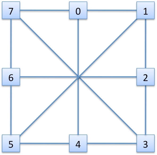 |
Processing nodes
For a Spidergon ring, each processing node is identified by only 1
integer between 0 and 8. Create a file "spidergon.top" and add the
following lines:This indicates that the maximum number of faulty channels is 0, each
processing node is identified by 1 field 's'. E.g. a processing node
in a 3D-mesh can be identified using three fields x, y and z. The value
of s ranges from 0 to 7.
This connects each accross channel to the processing node accross, each
clockwise channel to the processing node next
in the ring, etc.
The complete topology file for the Spidergon can be downloaded here. As another example, download the topology file for a 3D-mesh here.
Resources
There are three types of channels: clockwise, counter-clockwise or accross. Also, we need a local channel. We add to the file:Topology
The topology is specified using two C functions. One which given a channel returns the processing node at the source of the channel, one which given a channel returns the processing node at the end of the channel.The complete topology file for the Spidergon can be downloaded here. As another example, download the topology file for a 3D-mesh here.
| <- step 1 -> |
<-
step 3 -> |